


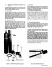
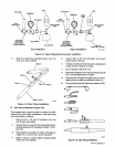
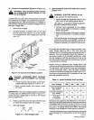
11.
Insert
the
1/4-20
setscrews
into
center
and
bot-
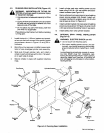
1.
Open
access
door.
torn
holes
in
jack
plug,
and
tighten
(E).
2.
Loosen
the
gun/feeder
connector
securing
knob
12.
Remove
cable
from
vise,
and
insert
jack
plug
into
(see
Figure
4-7).
insulating
sleeve.
Slide
insulating
sleeve
over
jack
plug
and
cable
until
hole
in
insulating
sleeve
IMPORTANT:
Wire
guides
should
be
installed
so
that
lines
up
with
rernaining
hole
in
jack
plug
(F).
the
tip
of
the
guide
is
as
close
to
the
drive
rolls
as
possi
ble
without
touching.
13.
Insert
the
8-32
self-tapping
screw
(F)
through
hole
in
insulating
sleeve
into
jack
plug,
and
tight-
3.
Insert
the
gun/feeder
connector,
which
includes
en.
outlet
guide,
through
the
access
hole
in
the
weld-
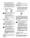
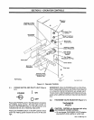
4-7.
WELD
POLARITY
SELECTION
ing
power
source
front
panel
and
into
the
drive
as
sembly
as
illustrated
in
Figures
4-7
and
4-8.
NEGATIVE
POSITIVE
4.
Tighten
the
gun/feeder
connector
securing
knob.
5.
Close
and
secure
access
door.
1
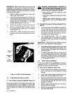
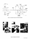
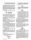
B.
Gun
Switch
Connection
(Figure
4-8)
a
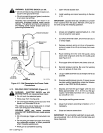
WARNING:
ELECTRIC
SHOCKcan
kill;
ARC
ING
can
burn
skin
or
damage
electrical
con-
GUN
nections.
TRIGGER
Do
not
touch
live
electrical
parts.
Shut
down
welding
power
source
before
mak
ing
any
twistlock
plug
connections.
The
GUN
TRIGGER
receptacle
is
provided
for
making
Do
not
change
position
oftwistlockplug
while
switch
control
connections.
Align
the
keys
on
the
gun
welding.
switch
connector
with
the
keyway
on
the
GUN
TRIG-
Secure
twistlock
plug
in
selected
receptacle
GER
receptacle,
insert
connector,
and
rotate
threaded
before
welding.
collar
fully
clockwise.
When
the
gun
switch
is
closed,
the
IMPORTANT:
Rotate
jack
plugs
1/4
turn
clockwise
to
welding
power
source
contactor
energizes,
shielding
secure
them
in
receptacles,
gas
flows,
and
wire
feeds.
1.
Connect
jack
plug
on
weld
cable
from
unit
into
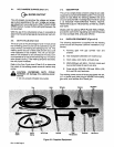
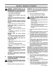
4-9.
INSTALLATION
OF
OPTIONAL
SPOOL
GUN
POSITIVE
(+)
weld
output
receptacle.
~
WARNING:
ELECTRIC
SHOCK
can
kill.
2.
Connect
jack
plug
from
work
cable
into
NEGA-
~
Do
not
touch
live
electrical
parts.
TIVE
()
weld
output
receptacle.
IMPORTANT:
For
Electrode
Negative/Straight
Polarity
Do
not
connect
two
guns
to
this
welding
pow
er
source
at
the
same
time.
Connections,
reverse
cable
connections
to
weld
output
receptacles;
electrode
becomes
negative.
Shut
down
welding
power
source,
and
dis
connect
input
power
employing
lockout/tag
ging
procedures
before
inspecting
or
install-
4-8.
MWG-200
WELDING
GUN
CONNECTIONS
ing.
~
WARNING:
ELECTRIC
SHOCK
can
kill.
Lockout/tagging
procedures
consist
of
remov
Do
not
touch
live
electrical
parts.
ing
input
power
plug
from
receptacle,
pad
locking
line
disconnect
switch
in
open
position,
Shut
down
welding
power
source,
and
dis-
removing
fuses
from
fuse
box,
or
shutting
off
connect
input
power
employing
lockout/tag-
and
red-tagging
circuit
breaker
or
other
discon
ging
procedures
before
inspecting
or
install-
necting
device.
ing.
If
two
guns
are
connected
to
this
welding
power
Lockout/tagging
procedures
consist
of
remov-
source,
both
electrode
wires
will
be
energized
ing
input
power
plug
from
receptacle,
pad-
when
either
gun
is
operated.
locking
line
disconnect
switch
in
open
position,
removing
fuses
from
fuse
box,
or
shutting
off
and
red-tagging
circuit
breaker
or
other
discon-
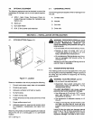
A.
Shielding
Gas
Connections
necting
device.
IMPORTANT:
Use
pure
argon
shielding
gas
for
alumi
num
wire
welding.
A.
Gun/Feeder
Connector
Installation
(Figures
4-7
And
4-8)
Connect
the
shielding
gas
hose
from
the
Spool
Gun
to
IMPORTANT:
The
outlet
guide
is
provided
as
part
of
the
the
gas
regulator/flowmeter
on
the
shielding
gas
supply.
gun
assembly.
The
connector
has
5/8-18
right-hand
threads.
OM-113
336
Page
14