


882.00207.00 Chapter 2: Functional Description 27 of 102
2-5 Safety Features
This section includes information on important safety devices and procedures relating to the
Gravimetric Batch Blender. This manual is not intended to supersede or alter safety standards
established by the user of this equipment. Instead, the material contained in this section is
recommended to supplement these procedures in order to provide a safer working environment.
At the completion of this section, the operator and maintenance personnel will be able to do the
following:
• Identify and locate specific safety devices.
• Understand the proper use of the safety devices provided.
• Describe the function of the safety device.
Safety Circuit Standards
Safety circuits used in industrial systems protect the operator and maintenance personnel from
dangerous energy. They also provide a means of locking out or isolating the energy for servicing
equipment.
Various agencies have contributed to the establishment of safety standards that apply to the design
and manufacture of automated equipment. The Occupational Safety and Health Administration
(OSHA) and the Joint Industrial council (JIC) are just a few of the organizations that have joined
with the plastics industry to develop safety standards.
Every effort has been made to incorporate these standards into the design of the Slide Gate/Auger
Blender; however, it is the responsibility of the personnel operating and maintaining the equipment
to familiarize themselves with the safety procedures and the proper use of any safety devices.
Fail Safe Operation
If a safety device or circuit should fail, the design must be such that the failure causes a “Safe”
condition. As an example, a safety switch must be a normally open switch. The switch must be held
closed with the device it is to protect. If the switch fails it will go to the open condition, tripping out
the safety circuit.
At no time should the safety device fail and allow the operation to continue. For example, if a
safety switch is guarding a motor and the safety switch fails, the motor should not be able to run.
Safety Device Lock-Outs
Some safety devices disconnect electrical energy from a circuit. The safety devices that are used on
the Slide Gate/Auger Blenders are primarily concerned with pneumatic and electrical power
disconnection and the disabling of moving parts that may need to be accessed during the normal
operation of the machine.
Some of the safety devices utilize a manual activator. This is the method of initiating the safety lock
out. This may be in the form of a plug, lever or a handle. Within this lockable handle, there may be
a location for a padlock. Personnel servicing the equipment should place a padlock in the lockout
handle.
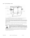
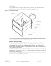
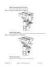
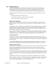
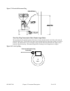
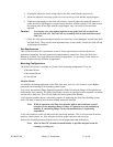
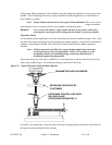
In addition to the safety devices listed above, these blenders are equipped with a line cord plug
(Shown in figures 17 and 18). This allows the operator or maintenance personnel to unplug the unit
from its power source and tag it out. The plug can then be tagged with any number of approved
electrical lockout tags available at most electrical supply stores.