


882.00207.00 Chapter 3: Installation 31 of 102
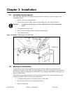
4. If equipped, adjust the four leveling bolts on the floor stand blender support rails.
5. Mount the material conveying system receivers on the top of the blender supply hoppers.
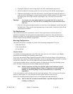
6. Align the weigh hopper on the load cell brackets. Carefully adjust the load cell brackets to
ensure that the weigh hopper is centered on the brackets without rocking. If for some reason
the locating tabs do not align with the weigh hopper, they can easily be loosened and
adjusted.
Caution! Use extreme care when tightening bolts on top of the load cells so you do not
spring the load cells. The load cells are extremely delicate and should be treated
with care!
7. Check the slide gate metering assemblies to ensure they are not damaged, and will slide back
and forth freely. These are the most important items on the blender, besides the load cell and
weigh hopper assemblies.
Site Requirements
This section describes site requirements in detail. These requirements are broken down into
mechanical mounting, electrical connections and pneumatic connections. Since the Slide Gate
Blender is available in several different mounting arrangements, it is necessary for the reader to
become familiar with the different arrangements.
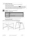
Mounting Configurations
The Slide Gate System is available in (3) three basic mounting arrangements. They are:
• Machine Mount
• Mezzanine Mount
• Floor Mount
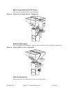
Machine Mount
In a machine mounting application of the Slide Gate unit, there are a few items to review before
placement and mounting of the blending system begins.
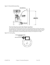
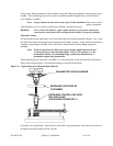
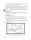
First, verify the machine flange dimensions match the Slide Gate blender flange (if the optional pre-
drilled holes were ordered). The Slide Gate blender can also be equipped with an optional cast throat
section with a drain port. This will bolt under the bottom plate of the blender.
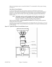
Verify that the machine throat is physically capable of supporting the Slide Gate blending system
with a full load of material and vacuum loading equipment installed.
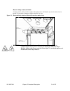
Verify all clearances on the top and beside the processing machine. This is to insure that all motors,
hoppers, control panels, etc. have adequate room for proper operation and servicing.
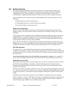
Refer to the assembly drawing with the unit for actual height and width dimensions.
Note: While in operation, the Slide Gate blender applies horizontal and vertical
pressures to the mounting flange. If there is a question as to the mechanical
stability of a mounting flange, contact the manufacturer’s engineering
department.
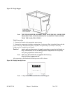
Note: Allow at least 36” clearance around blender to provide adequate room for
cleaning, servicing, etc.