


882.00207.00 Chapter 5: Maintenance 65 of 102
Input Signals to Programmable Controller
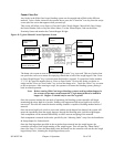
The Slide Gate/Auger blending system has two main input signals that it uses from the blending
process: the mix hopper high level signal and the weigh hopper load cells. This, of course, does not
include the operator touchscreen input.
The mix hopper high level signal is generated by a proximity level sensor located in the right hand
portion of the mixer chamber (viewing from the mixer door).
Load cells require +10 volts DC to operate. This is known as the load cell’s excitation voltage.
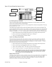
Output Signals from Programmable Controller
The Slide Gate/Auger blending system uses several output control signals to control the process. All
of these are very similar in nature, the first of which is the mixer motor control.
The mixer motor is controlled by a PLC output.
The weigh hopper dump valve output functions similar to the mix motor output. Please refer back to
the wiring diagram. The origin of the weigh hopper dump signal is a PLC output.
The auger motor outputs are driven from a control output from the PLC.
Each blending system includes an auxiliary customer alarm output. This dry contact can be used to
switch a remote alarm signal.
The customer alarm output is provided to actuate or energize a variety of alarm horns, buzzers,
strobe lights, and beacons. These are normally provided by the customer, and care will have to
be exercised not to exceed the maximum current draw (3 amp maximum). The contacts will
close whenever the control detects a fault that will somehow inhibit the blending system from
properly blending the material.
Note: The customer alarm contact is open if the panel control power is turned off.
This contact is for use with a customer supplied alarm device as described
above. The alarm contact has a maximum load of 3 amps.