


Interface
5-30 C141-E050-02EN
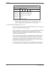
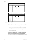
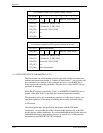
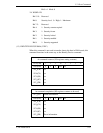
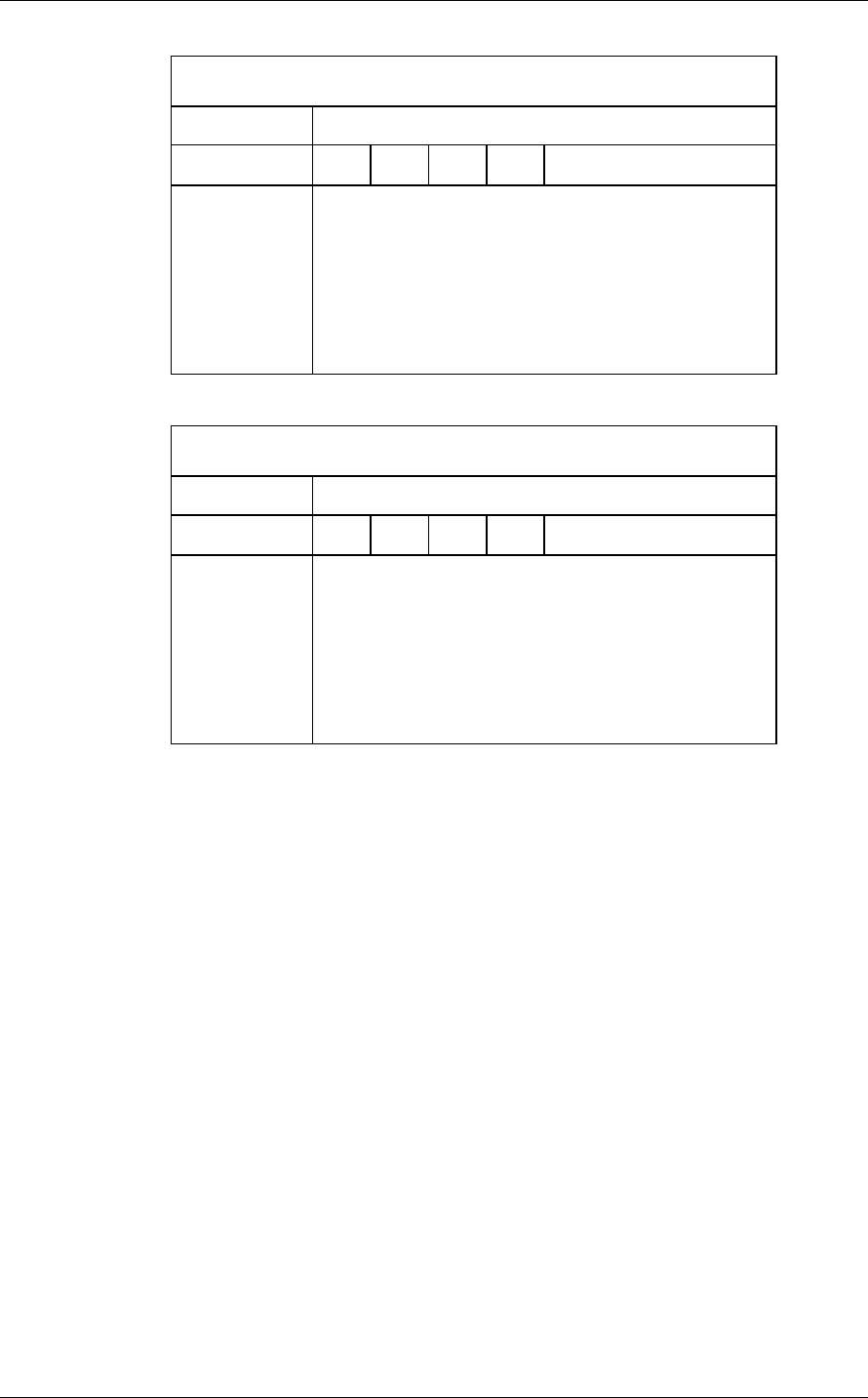
At command issuance (I/O registers setting contents)
1F7
H
(CM)
0 1 1 1
x
x
x
x
1F6
H
(DH)
×
L
×
DV
Head No. /LBA [MSB]
1F5
H
(CH)
1F4
H
(CL)
1F3
H
(SN)
1F2
H
(SC)
1F1
H
(FR)
Cylinder No. [MSB] / LBA
Cylinder No. [LSB] / LBA
Sector No. / LBA [LSB]
xx
xx
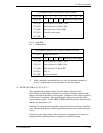
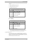
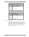
At command completion (I/O registers contents to be read)
1F7
H
(ST)
Status information
1F6
H
(DH)
×
L
×
DV
Head No. /LBA [MSB]
1F5
H
(CH)
1F4
H
(CL)
1F3
H
(SN)
1F2
H
(SC)
1F1
H
(ER)
Cylinder No. [MSB] / LBA
Cylinder No. [LSB] / LBA
Sector No. / LBA [LSB]
xx
Error information
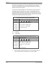
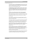
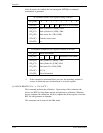
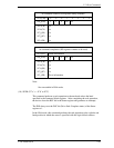
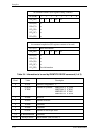
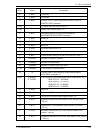
(11) INITIALIZE DEVICE PARAMETERS (X’91’)
The host system can set the number of sectors per track and the maximum head
number (maximum head number is “number of heads minus 1”) per cylinder with
this command. Upon receipt of this command, the device sets the BSY bit of
Status register and saves the parameters. Then the device clears the BSY bit and
generates an interrupt.
When the SC register is specified to X’00’, an ABORTED COMMAND error is
posted. Other than X’00’ is specified, this command terminates normally.
The parameters set by this command are retained even after reset or power save
operation regardless of the setting of disabling the reverting to default setting.
In LBA mode
The device ignores the L bit specification and operates with the CHS mode
specification. An accessible area of this command within head moving in the LBA
mode is always within a default area. It is recommended that the host system refers the
addressable user sectors (total number of sectors) in word 60 to 61 of the parameter
information by the IDENTIFY DEVICE command.