


Interface
5-52 C141-E050-02EN
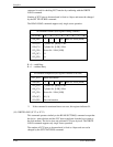
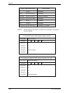
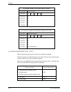
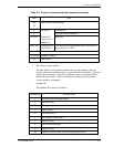
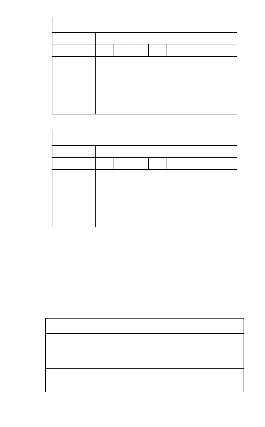
At command issuance (I/O registers setting contents)
1F7
H
(CM)
X’99’ or X’E6’
1F6
H
(DH)
× × ×
DV
xx
1F5
H
(CH)
1F4
H
(CL)
1F3
H
(SN)
1F2
H
(SC)
1F1
H
(FR)
xx
xx
xx
xx
xx
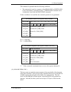
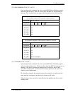
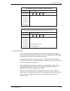
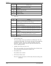
At command completion (I/O registers contents to be read)
1F7
H
(ST)
Status information
1F6
H
(DH)
× × ×
DV
xx
1F5
H
(CH)
1F4
H
(CL)
1F3
H
(SN)
1F2
H
(SC)
1F1
H
(ER)
xx
xx
xx
xx
Error information
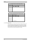
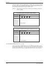
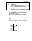
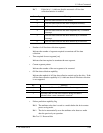
(26) CHECK POWER MODE (X’98’ or X’E5’)
The host checks the power mode of the device with this command.
The host system can confirm the power save mode of the device by analyzing the
contents of the Sector Count and Sector registers.
The device sets the BSY bit and sets the following register value. After that, the
device clears the BSY bit and generates an interrupt.
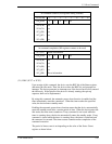
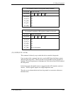
Power save mode
Sector Count register
• During moving to standby mode
• Standby mode
• During returning from the standby mode
X’00’
• Idle mode
X’FF’
• Active mode
X’FF’