


Interface
5-42 C141-E050-02EN
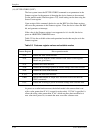
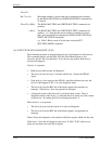
Word 47
Bit 7-0 = 10:
Word 59 = 0000:
= 00xx:
Maximum number of sectors that can be transferred per interrupt
by the READ MULTIPLE and WRITE MULTIPLE commands are
16 (fixed).
The READ MULTIPLE and WRITE MULTIPLE commands are
disabled.
The READ MULTIPLE and WRITE MULTIPLE commands are
enabled.
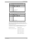
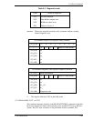
“
xx
”
indicates the current setting for number of sectors
that can be transferred per interrupt by the READ MULTIPLE and
WRITE MULTIPLE commands.
e.g. 0010 = Block count of 16 has been set by the SET
MULTIPLE MODE command.
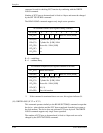
(16) EXECUTE DEVICE DIAGNOSTIC (X’90’)
This command performs an internal diagnostic test (self-diagnosis) of the device.
This command usually sets the DRV bit of the Drive/Head register is to 0
(however, the DV bit is not checked). If two devices are present, both devices
execute self-diagnosis.
If device 1 is present:
• Both devices shall execute self-diagnosis.
• The device 0 waits for up to 5 seconds until device 1 asserts the PDIAG-
signal.
• If the device 1 does not assert the PDIAG- signal but indicates an error, the
device 0 shall append X’80’ to its own diagnostic status.
• The device 0 clears the BSY bit of the Status register and generates an
interrupt. (The device 1 does not generate an interrupt.)
• A diagnostic status of the device 0 is read by the host system. When a
diagnostic failure of the device 1 is detected, the host system can read a status
of the device 1 by setting the DV bit (selecting the device 1).
When device 1 is not present:
• The device 0 posts only the results of its own self-diagnosis.
• The device 0 clears the BSY bit of the Status register, and generates an
interrupt.
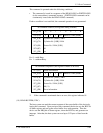
Table 5.6 lists the diagnostic code written in the Error register which is 8-bit code.
If the device 1 fails the self-diagnosis, the device 0 “ORs” X’80’ with its own
status and sets that code to the Error register.