


Interface
5-18 C141-E050-02EN
Command block registers contain the cylinder, the head, and the sector addresses
of the sector (in the CHS mode) or the logical block address (in the LBA mode)
where the error occurred, and remaining number of sectors of which data was not
transferred.
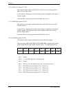
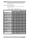
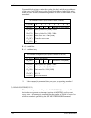
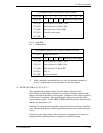
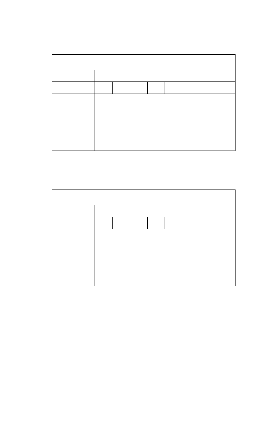
At command issuance (I/O registers setting contents)
1F7
H
(CM)
0 0 1 0 0 0 0 R
1F6
H
(DH)
×
L
×
DV
Start head No. /LBA [MSB]
1F5
H
(CH)
1F4
H
(CL)
1F3
H
(SN)
1F2
H
(SC)
1F1
H
(FR)
Start cylinder No. [MSB] / LBA
Start cylinder No. [LSB] / LBA
Start sector No. / LBA [LSB]
Transfer sector count
xx
R = 0 →with Retry
R = 1
→without Retry
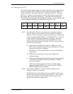
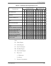
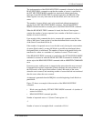
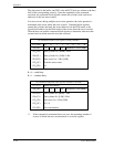
At command completion (I/O registers contents to be read)
1F7
H
(ST)
Status information
1F6
H
(DH)
×
L
×
DV
End head No. /LBA [MSB]
1F5
H
(CH)
1F4
H
(CL)
1F3
H
(SN)
1F2
H
(SC)
1F1
H
(ER)
End cylinder No. [MSB] / LBA
End cylinder No. [LSB] / LBA
End sector No. / LBA [LSB]
00 (*1)
Error information
*1 If the command is terminated due to an error, the remaining number of
sectors of which data was not transferred is set in this register.
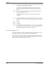
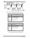
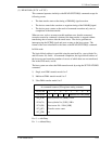
(2) READ MULTIPLE (X’C4’)
This command operates similarly to the READ SECTOR(S) command. The
device does not generate an interrupt (assertion of the INTRQ signal) on each
every sector. An interrupt is generateed after the transfer of a block of sectors for
which the number is specified by the SET MULTIPLE MODE command.