


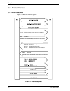

5.1 Physical Interface
C141-E050-02EN 5-5
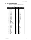
[signal]
[I/O]
[Description]
IOCS16-
O
This signal indicates 16-bit data bus is addressed in PIO data transfer.
This signal is an open collector output.
−
When IOCS16- is not asserted:
8 bit data is transferred through DATA0 to DATA7 signals.
−
When IOCS16- is asserted:
16 bit data is transferred through DATA0 to DATA15 signals.
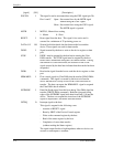
CS0-
I
Chip select signal decoded from the host address bus. This signal
is used by the host to select the command block registers.
CS1-
I
Chip select signal decoded from the host address bus. This signal
is used by the host to select the control block registers.
DA 0-2
I
Binary decoded address signals asserted by the host to access task
file registers.
KEY
-
Key pin for prevention of erroneous connector insertion
PDIAG-
I/O
This signal is an input mode for the master device and an output
mode for the slave device in a daisy chain configuration. This
signal indicates that the slave device has been completed self
diagnostics.
This signal is pulled up to +5 V through 10 k
Ω
resistor at each device.
DASP-
I/O
This is a time-multiplexed signal that indicates that the device is
active and a slave device is present.
This signal is pulled up to +5 V through 10 k
Ω
resistor at each device.
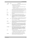
IORDY
O
This signal requests the host system to delay the transfer cycle
when the device is not ready to respond to a data transfer request
from the host system.
DDMARDY
-
O
Flow control signal for Ultra DMA data Out transfer (WRITE
DMA command). This signal is asserted by the device to inform
the host that the device is ready to receive the Ultra DMA data
Out transfer. The device can negate the DDMARDY- signal to
suspend the Ultra DMA data Out transfer.
DSTROBE
O
Data In Strobe signal from the device during Ultra DMA data In
transfer. Both the rising and falling edges of the DSTROBE
signal latch data from Data 15-0 into the host. The device can
suspend the inversion of the DSTROBE signal to suspend the
Ultra DMA data In transfer.
CSEL
I
This signal to configure the device as a master or a slave device.
−
When CSEL signal is grounded,, the IDD is a master device.
−
When CSEL signal is open,, the IDD is a slave device.
This signal is pulled up with 240 k
Ω
resistor at each device.
DMACK-
I
The host system asserts this signal as a response that the host
system receive data or to indicate that data is valid.