


Interface
5-8 C141-E050-02EN
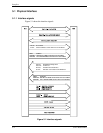
5.2.2 Command block registers
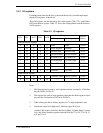
(1) Data register (X’1F0’)
The Data register is a 16-bit register for data block transfer between the device and
the host system. Data transfer mode is PIO or DMA mode.
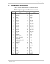
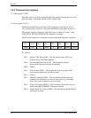
(2) Error register (X’1F1’)
The Error register indicates the status of the command executed by the device.
The contents of this register are valid when the ERR bit of the Status register is 1.
This register contains a diagnostic code after power is turned on, a reset , or the
EXECUTIVE DEVICE DIAGNOSTIC command is executed.
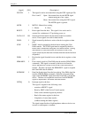
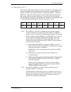
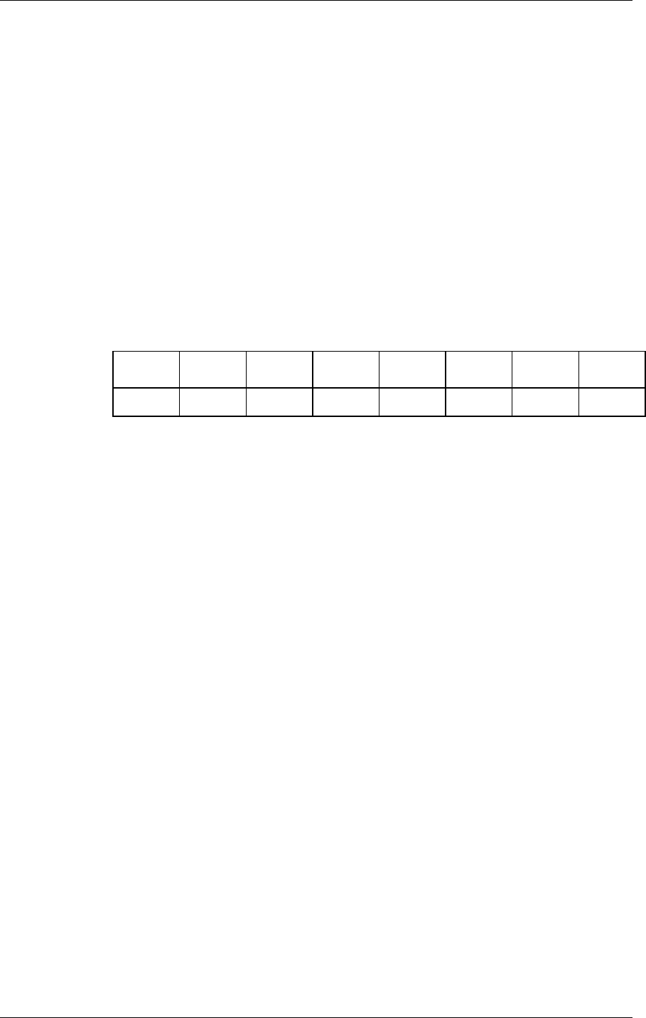
[Status at the completion of command execution other than diagnostic command]
Bit 7
Bit 6
Bit 5
Bit 4
Bit 3
Bit 2
Bit 1
Bit 0
ICRC UNC X IDNF X ABRT TK0NF AMNF
X: Unused
- Bit 7:
Interface CRC Error (ICRC). This bit indicates that a CRC error
occurred during Ultra DMA transfer.
- Bit 6:
Uncorrectable Data Error (UNC). This bit indicates that an
uncorrectable data error has been encountered.
- Bit 5:
Unused
- Bit 4:
ID Not Found (IDNF). This bit indicates an error except for bad
sector, uncorrectable error and SB not found.
- Bit 3:
Unused
- Bit 2:
Aborted Command (ABRT). This bit indicates that the requested
command was aborted due to a device status error (e.g. Not Ready,
Write Fault) or the command code was invalid.
- Bit 1:
Track 0 Not Found (TK0NF). This bit indicates that track 0 was not
found during RECALIBRATE command execution.
- Bit 0:
Address Mark Not Found (AMNF). This bit indicates that the SB Not
Found error occurred.