


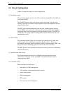
Theory of Device Operation
4-12 C141-E050-02EN
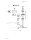
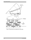
4.6.3 Read circuit
The head read signal from the PreAMP is regulated by the automatic gain control
(AGC) circuit. Then the output is converted into the sampled read data pulse by
the programmable filter circuit and the flash digitizer circuit. This clock signal is
converted into the NRZ data by the 16/17 GCR decoder circuit based on the read
data maximum-likelihood-detected by the Viterbi detection circuit, then is sent to
the HDC.
(1) AGC circuit
The AGC circuit automatically regulates the output amplitude to a constant value
even when the input amplitude level fluctuates. The AGC amplifier output is
maintained at a constant level even when the head output fluctuates due to the
head characteristics or outer/inner head positions.
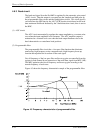
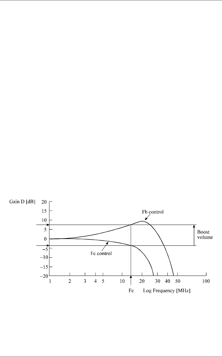
(2) Programmable filter
The programmable filter circuit has a low-pass filter function that eliminates
unnecessary high frequency noise component and a high frequency boost-up
function that equalizes the waveform of the read signal.
Cut-off frequency of the low-pass filter and boost-up gain are controlled from the
register in read channel by an instruction of the serial data signal from MPU (M5).
The MPU optimizes the cut-off frequency and boost-up gain according to the
transfer frequency of each zone.
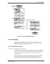
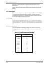
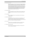
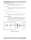
Figure 4.5 shows the frequency characteristic sample of the programmalbe filter.
Figure 4.5 Frequency characteristic of programmable filter
-3 dB