


Interface
5-40 C141-E050-02EN
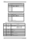
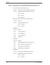
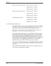
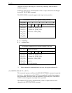
Single word DMA transfer mode X 00010 000 (X’10’: Mode 0)
00010 001 (X’11’: Mode 1)
00010 010 (X’12’: Mode 2)
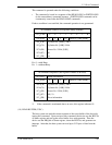
Multiword DMA transfer mode X 00100 000 (X’20’: Mode 0)
00100 001 (X’21’: Mode 1)
00100 010 (X’22’: Mode 2)
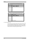
Ultra DMA transfer mode X 01000 000 (X’40’: Mode 0)
01000 001 (X’41’: Mode 1)
01000 010 (X’42’: Mode 2)
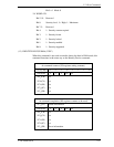
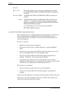
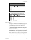
(15) SET MULTIPLE MODE (X’C6’)
This command enables the device to perform the READ MULTIPLE and WRITE
MULTIPLE commands. The block count (number of sectors in a block) for these
commands are also specified by the SET MULTIPLE MODE command.
The number of sectors per block is written into the Sector Count register. The
IDD supprots 2, 4, 8, 16 and 32 (sectors) as the block counts.
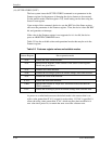
Upon receipt of this command, the device sets the BSY bit of the Status register
and checks the contents of the Sector Count register. If the contents of the Sector
Count register is valid and is a supported block count, the value is stored for all
subsequent READ MULTIPLE and WRITE MULTIPLE commands. Execution
of these commands is then enabled. If the value of the Sector Count register is not
a supported block count, an ABORTED COMMAND error is posted and the
READ MULTIPLE and WRITE MULTIPLE commands are disabled.
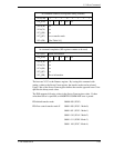
If the contents of the Sector Count register is 0 when the SET MULTIPLE MODE
command is issued, the READ MULTIPLE and WRITE MULTIPLE commands
are disabled.
When the SET MULTIPLE MODE command operation is completed, the device
clears the BSY bit and generates an interrupt.