


Theory of Device Operation
4-20 C141-E050-02EN
d) If the head is stopped at the reference cylinder from there. Track following
control starts.
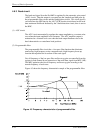
(2) Seek operation
Upon a data read/write request from the host, the MPU confirms the necessity of
access to the disk. If a read/write instruction is issued, the MPU seeks the desired
track.
The MPU feeds the VCM current via the D/A converter and power amplifier to
move the head. The MPU calculates the difference (speed error) between the
specified target position and the current position for each sampling timing during
head moving. The MPU then feeds the VCM drive current by setting the
calculated result into the D/A converter. The calculation is digitally executed by
the firmware. When the head arrives at the target cylinder, the track is followed.
(3) Track following operation
Except during head movement to the reference cylinder and seek operation under
the spindle rotates in steady speed, the MPU does track following control. To
position the head at the center of a track, the DSP drives the VCM by feeding
micro current. For each sampling time, the VCM drive current is determined by
filtering the position difference between the target position and the position
clarified by the detected position sense data. The filtering includes servo
compensation. These are digitally controlled by the firmware.
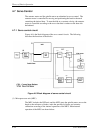
4.7.5 Spindle motor control
Hall-less three-phase twelve-pole motor is used for the spindle motor, and the 3-
phase full/half-wave analog current control circuit is used as the spindle motor
driver (called SVC hereafter). The firmware operates on the MPU manufactured
by Fujitsu. The spindle motor is controlled by sending several signals from the
MPU to the SVC. There are three modes for the spindle control; start mode,
acceleration mode, and stable rotation mode.
(1) Start mode
When power is supplied, the spindle motor is started in the following sequence:
a) After the power is turned on, the MPU sends a signal to the SVC to charge
the charge pump capacitor of the SVC. The charged amount defines the
current that flows in the spindle motor.
b) When the charge pump capacitor is charged enough, the MPU sets the SVC
to the motor start mode. Then, a current (approx. 0.7 A) flows into the
spindle motor.
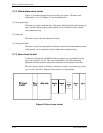
c) The SVC generates a phase switching signal by itself, and changes the phase
of the current flowed in the motor in the order of (V-phase to U-phase), (W-
phase to U-phase), (W-phase to V-phase), (U-phase to V-phase), (U-phase to
W-phase), and (V-phase to W-phase) (after that, repeating this order).