


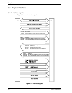

5.2 Logical Interface
C141-E050-02EN 5-9
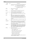
[Diagnostic code]
X’01’:
No Error Detected.
X’02’:
HDC Register Compare Error
X’03’:
Data Buffer Compare Error.
X’05’:
ROM Sum Check Error.
X’80’:
Device 1 (slave device) Failed.
Error register of the master device is valid under two devices (master
and slave) configuration. If the slave device fails, the master device
posts X’80’ OR (the diagnostic code) with its own status (X’01’ to
X’05’).
However, when the host system selects the slave device, the diagnostic
code of the slave device is posted.
(3) Features register (X’1F1’)
The Features register provides specific feature to a command. For instance, it is
used with SET FEATURES command to enable or disable caching.
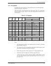
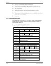
(4) Sector Count register (X’1F2’)
The Sector Count register indicates the number of sectors of data to be transferred
in a read or write operation between the host system and the device. When the
value in this register is X’00’, the sector count is 256.
When this register indicates X’00’ at the completion of the command execution,
this indicates that the command is completed succefully. If the command is not
completed scuccessfully, this register indicates the number of sectors to be
transferred to complete the request from the host system. That is, this register
indicates the number of remaining sectors that the data has not been transferred
due to the error.
The contents of this register has other definition for the following commands;
INITIALIZE DEVICE PARAMETERS, SET FEATURES, IDLE, STANDBY
and SET MULTIPLE MODE.
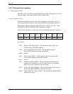
(5) Sector Number register (X’1F3’)
The contents of this register indicates the starting sector number for the
subsequent command. The sector number should be between X’01’ and [the
number of sectors per track defined by INITIALIZE DEVICE PARAMETERS
command.
Under the LBA mode, this register indicates LBA bits 7 to 0.