


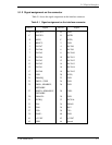

5.2 Logical Interface
C141-E050-02EN 5-11
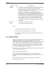
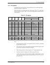
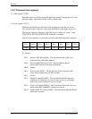
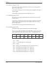
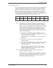
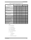
(9) Status register (X’1F7’)
The contents of this register indicate the status of the device. The contents of this
register are updated at the completion of each command. When the BSY bit is
cleared, other bits in this register should be validated within 400 ns. When the
BSY bit is 1, other bits of this register are invalid. When the host system reads
this register while an interrupt is pending, it is considered to be the Interrupt
Acknowledge (the host system acknowledges the interrupt). Any pending interrupt
is cleared (negating INTRQ signal) whenever this register is read.
Bit 7
Bit 6
Bit 5
Bit 4
Bit 3
Bit 2
Bit 1
Bit 0
BSY DRDY DF DSC
DRQ
0 0 ERR
- Bit 7:
Busy (BSY) bit. This bit is set whenever the Command register is
accessed. Then this bit is cleared when the command is completed.
However, even if a command is being executed, this bit is 0 while data
transfer is being requested (DRQ bit = 1).When BSY bit is 1, the host
system should not write the command block registers. If the host
system reads any command block register when BSY bit is 1, the
contents of the Status register are posted. This bit is set by the device
under following conditions:
(a) Within 400 ns after RESET- is negated or SRST is set in the
Device Control register, the BSY bit is set. the BSY bit is cleared,
when the reset process is completed.
The BSY bit is set for no longer than 15 seconds after the IDD
accepts reset.
(b) Within 400 ns from the host system starts writing to the
Command register.
(c) Within 5
µ
s following transfer of 512 bytes data during execution
of the READ SECTOR(S), WRITE SECTOR(S), or WRITE
BUFFER command.
Within 5
µ
s following transfer of 512 bytes of data and the
appropriate number of ECC bytes during execution of READ
LONG or WRITE LONG command.
- Bit 6:
Device Ready (DRDY) bit. This bit indicates that the device is
capable to respond to a command.
The IDD checks its status when it receives a command. If an error is
detected (not ready state), the IDD clears this bit to 0. This is cleared
to 0 at power-on and it is cleared until the rotational speed of the
spindle motor reaches the steady speed.