


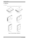

Installation Conditions
3-12 C141-E050-02EN
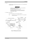
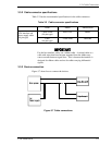
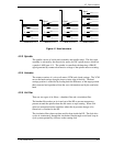
3.4.4 CSEL setting
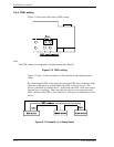
Figure 3.12 shows the cable select (CSEL) setting.
Note:
The CSEL setting is not depended on setting between pins Band D.
Figure 3.12 CSEL setting
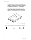
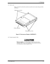
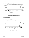
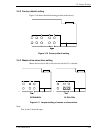
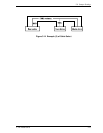
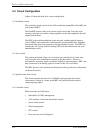
Figure 3.13 and 3.14 show examples of cable selection using unique interface
cables.
By connecting the CSEL of the master device to the CSEL Line (conducer) of the
cable and connecting it to ground further, the CSEL is set to low level. The
device is identified as a master device. At this time, the CSEL of the slave device
does not have a conductor. Thus, since the slave device is not connected to the
CSEL conductor, the CSEL is set to high level. The device is identified as a slave
device.
Figure 3.13 Example (1) of Cable Select
2