


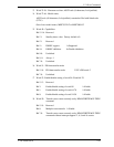

5.3 Host Commands
C141-E050-02EN 5-35
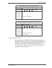
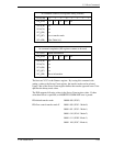
*3 Word 23-26: Firmware revision; ASCII code (8 characters, Left-justified)
*4 Word 27-46: Model name;
ASCII code (40 characters, Left-justified), remainder filled with blank code
(X’20’)
One of two model names; MHC2032AT or MHC2040AT
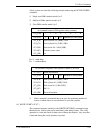
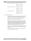
*5 Word 49: Capabilities
Bit 15-14: Reserved
Bit 13: Standby timer value. Factory default is 0.
Bit 12: Reserved
Bit 11: IORDY support 1=Supported
Bit 10: IORDY inhibition 0=Disable inhibition
Bit 9-0: Undefined
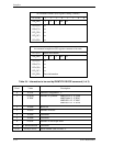
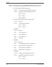
Bit 9, 8: Always 1
Bit 7-0: Undefined
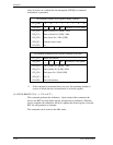
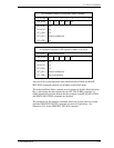
*6 Word 51: PIO data transfer mode
Bit 15-8: PIO data transfer mode X’02’=PIO mode 2
Bit 7-0: Undefined
*7 Word 53: Enable/disable setting of word 54-58 and 64-70
Bit 15-3: Reserved
Bit 2: Enable/disable setting of word 88 1=Enable
Bit 1: Enable/disable setting of word 64-70 1=Enable
Bit 0: Enable/disable setting of word 54-58 1=Enable
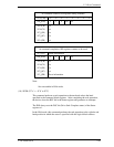
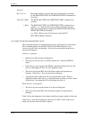
*8 Word 59: Transfer sector count currently set by READ/WRITE MULTIPLE
command
Bit 15-9: Reserved
Bit 8: Multiple sector transfer 1=Enable
Bit 7-0: Transfer sector count currently set by READ/WRITE MULTIPLE
command without interrupt supports 2, 4, 8 and 16 sectors.