


5.3 Host Commands
C141-E050-02EN 5-23
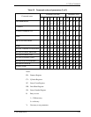
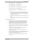
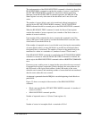
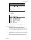
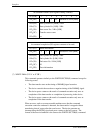
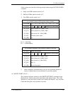
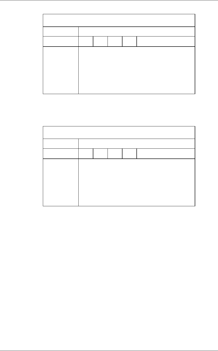
At command issuance (I/O registers setting contents)
1F7
H
(CM)
0 1 0 0 0 0 0 R
1F6
H
(DH)
×
L
×
DV
Start head No. /LBA [MSB]
1F5
H
(CH)
1F4
H
(CL)
1F3
H
(SN)
1F2
H
(SC)
1F1
H
(FR)
Start cylinder No. [MSB] / LBA
Start cylinder No. [LSB] / LBA
Start sector No. / LBA [LSB]
Transfer sector count
xx
R = 0 →with Retry
R = 1
→without Retry
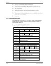
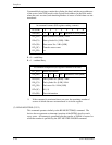
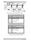
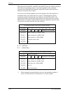
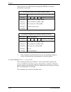
At command completion (I/O registers contents to be read)
1F7
H
(ST)
Status information
1F6
H
(DH)
×
L
×
DV
End head No. /LBA [MSB]
1F5
H
(CH)
1F4
H
(CL)
1F3
H
(SN)
1F2
H
(SC)
1F1
H
(ER)
End cylinder No. [MSB] / LBA
End cylinder No. [LSB] / LBA
End sector No. / LBA [LSB]
00 (*1)
Error information
*1 If the command is terminated due to an error, the remaining number of
sectors of which data was not transferred is set in this register.
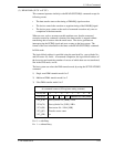
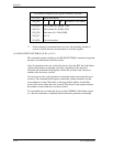
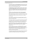
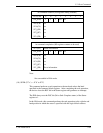
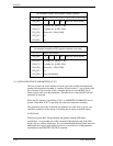
(5) WRITE SECTOR(S) (X’30’ or X’31’)
This command writes data of sectors from the address specified in the
Device/Head, Cylinder High, Cylinder Low, and Sector Number registers to the
address specified in the Sector Count register. Number of sectors can be specified
to 256 sectors in maximum. Data transfer begins at the sector specified in the
Sector Number register. For the DRQ, INTRQ, and BSY protocols related to data
transfer, see Subsection 5.4.2.
If the head is not on the track specified by the host, the device performs a implied
seek. After the head reaches to the the specified track, the device writes the target
sector.
If an error occurs when writing to the target sector, a maximum of 63 retries are
attempted before reporting the error, irrespective of the R bit setting.