


5.3 Host Commands
C141-E050-02EN 5-17
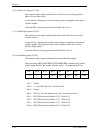
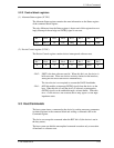
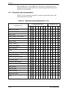
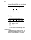
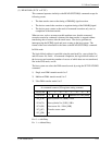
CM: Command register FR: Features register
DH: Device/Head register ST: Status register
CH: Cylinder High register ER: Error register
CL: Cylinder Low register L: LBA (logical block address) setting bit
SN: Sector Number register DV: Device address. bit
SC: Sector Count register x, xx: Do not care (no necessary to set)
Note:
1. When the L bit is specified to 1, the lower 4 bits of the DH register and all
bits of the CH, CL and SN registers indicate the LBA bits (bits of the DH
register are the MSB (most significant bit) and bits of the SN register are
the LSB (least significant bit).
2. At error occurrance, the SC register indicates the remaining sector count of data
transfer.
3. In the table indicating I/O registers contents in this subsection, bit indication is
omitted.
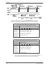
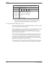
(1) READ SECTOR(S) (X’20’ or X’21’)
This command reads data of sectors specified in the Sector Count register from
the address specified in the Device/Head, Cylinder High, Cylinder Low and
Sector Number registers. Number of sectors can be specified to 256 sectors in
maximum. To specify 256 sectors reading, ‘00’ is specified. For the DRQ,
INTRQ, and BSY protocols related to data transfer, see Subsection 5.4.1.
If the head is not on the track specified by the host, the device performs a implied
seek. After the head reaches to the specified track, the device reads the target
sector.
A maximum of 252 retry reads are attempted to read the target sector before
reporting an error, irrespective of the R bit setting.
The DRQ bit of the Status register is always set prior to the data transfer
regardless of an error condition.
Upon the completion of the command execution, command block registers contain
the cylinder, head, and sector addresses (in the CHS mode) or logical block
address (in the LBA mode) of the last sector read.
If an error occurs in a sector, the read operation is terminated at the sector where the
error occured.