


Theory of Device Operation
4-4 C141-E050-02EN
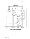
4.3 Circuit Configuration
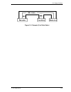
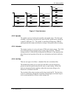
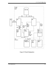
Figure 4.2 shows the disk drive circuit configuration.
(1) Read/write circuit
The read/write circuit consists of two LSIs; read/write preamplifier (PreAMP) and
read channel (RDC).
The PreAMP consists of the write current switch circuit, that flows the write
current to the head coil, and the voltage amplifier circuit, that amplitudes the read
output from the head.
The RDC is the read demodulation circuit using the extended partial response
class 4 (EPR4), and contains the Viterbi detector, programmable filter, adaptable
transversal filter, times base generator, and data separator circuits. The RDC also
contains the 16/17 group coded recording (GCR) encoder and decoder and servo
demodulation circuit.
(2) Servo circuit
The position and speed of the voice coil motor are controlled by 2 closed-loop
servo using the servo information recorded on the data surface. The servo
information is an analog signal converted to digital for processeing by a MPU and
then reconverted to an analog signal for control of the voice coil motor.
The MPU precisely sets each head on the track according on the servo information
on the media surface.
(3) Spindle motor driver circuit
The circuit measures the interval of a PHASE signal generated by counter-
electromotive voltage of a motor at the MPU and controls the motor speed
comparing target speed.
(4) Controller circuit
Major functions are listed below.
• Data buffer (512 KB) management
• ATA interface control and data transfer control
• Sector format control
• Defect management
• ECC control
• Error recovery and self-diagnosis