


4.7 Servo Control
C141-E050-02EN 4-21
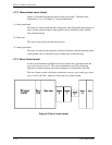
d) During phase switching, the spindle motor starts rotating in low speed, and
generates a counter electromotive force. The SVC detects this counter
electromotive force and reports to the MPU using a PHASE signal for speed
detection.
e) The MPU is waiting for a PHASE signal. When no phase signal is sent for a
sepcific period, the MPU resets the SVC and starts from the beginning.
When a PHASE signal is sent, the SVC enters the acceleration mode.
(2) Acceleration mode
In this mode, the MPU stops to send the phase switching signal to the SVC. The
SVC starts a phase switching by itself based on the counter electromotive force.
Then, rotation of the spindle motor accelerates. The MPU calcurates a rotational
speed of the spindle motor based on the PHASE signal from the SVC, and
accelerates till the rotational speed reaches 4,000 rpm. When the rotational speed
reaches 4,000 rpm, the SVC enters the stable rotation mode.
(3) Stable rotation mode
The MPU calcurates a time for one revolution of the spindle motor based on the
PHASE signal from the SVC. The MPU takes a difference between the current
time and a time for one revolution at 4,000 rpm that the MPU already recognized.
Then, the MPU keeps the rotational speed to 4,000 rpm by charging or
discharging the charge pump for the different time. For example, when the actual
rotational speed is 3,800 rpm, the time for one revolution is 15.789 ms. And, the
time for one revolution at 4,000 rpm is 15 ms. Therefore, the MPU charges the
charge pump for 0.789 ms
× k (k: constant value). This makes the flowed current
into the motor higher and the rotational speed up. When the actual rotational
speed is faster than 4,000 rpm, the MPU discharges the pump the other way. This
control (charging/discharging) is performed every 1 revolution.