


Contents
C141-E050-02EN xiii
Figure 5.5 WRITE SECTOR(S) command protocol 5-73
Figure 5.6 Protocol for the command execution without data transfer 5-
75
Figure 5.7 Normal DMA data transfer 5-76
Figure 5.8 An example of generation of parallel CRC 5-90
Figure 5.9 Ultra DMA termination with pull-up or pull-down 5-91
Figure 5.10 Data transfer timing 5-93
Figure 5.11 Single word DMA data transfer timing (mode 2) 5-94
Figure 5.12 Multiword DMA data transfer timing (mode 2) 5-95
Figure 5.13 Starting of Ultra DMA data In Burst transfer 5-96
Figure 5.14 Sustained Ultra DMA data in burst 5-99
Figure 5.15 Host pausing an Ultra DMA data in burst 5-100
Figure 5.16 Device terminating an Ultra DMA data in burst 5-101
Figure 5.17 Host terminating an Ultra DMA data in burst 5-102
Figure 5.18 Initiating an Ultra DMA data out burst 5-103
Figure 5.19 Sustained Ultra DMA data out burst 5-104
Figure 5.20 Device pausing an Ultra DMA data out burst 5-105
Figure 5.21 Host terminating an Ultra DMA data out burst 5-106
Figure 5.22 Device terminating an Ultra DMA data out burst 5-107
Figure 5.23 Power on Reset Timing 5-108
Figure 6.1 Response to power-on 6-3
Figure 6.2 Response to hardware reset 6-4
Figure 6.3 Response to software reset 6-5
Figure 6.4 Response to diagnostic command 6-6
Figure 6.5 Address translation (example in CHS mode) 6-8
Figure 6.6 Address translation (example in LBA mode) 6-9
Figure 6.7 Sector slip processing 6-12
Figure 6.8 Alternate cylinder assignment 6-13
Figure 6.9 Data buffer configuration 6-14
Tables
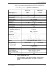
Table 1.1 Specifications (MHC2032AT/MHC2040AT) 1-4
Table 1.2 Specifications (MHD2021AT/MHD2032AT) 1-5
Table 1.3 Model names and product numbers 1-6
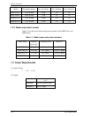
Table 1.4 Current and power dissipation 1-7
Table 1.5 Environmental specifications 1-8
Table 1.6 Acoustic noise specification 1-8
Table 1.7 Shock and vibration specification 1-9