


14 04581740_ed2
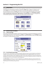
2.4.2 Bar Code Connection and Setup
Description
The bar code function allows the Insight IC controller to be connected to any serial ASCII bar code scanner or Ethernet
bar code scanner. Each spindle can be equipped with its own scanner or, in the case of a powerhead, one scanner can
be assigned to the powerhead. The bar code function has two main operating modes, Passive and Active. The choice of
bar code mode, along with all bar code operational settings, is made in the PC software. See the ICS software manual
for more information on selecting this option.
Passive Bar Code Mode
In this mode bar code data is attached to EOR data and stored in the cycle log, but Congurations are not selected via
the bar code scan data.
Active Bar Code Mode
In this mode Congurations are selected via the bar code scan data. The scan data is also attached to the EOR data. To
setup the controller for bar code operation, follow the directions below.
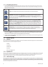
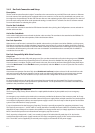
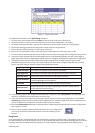
Bar Code Operation
When the bar code function is activated for a spindle, wherever the cycle data is sent (either Fieldbus, cycle log report,
EOR data or host data out), the bar code data is sent with it. Upon bootup, if a cycle is run before a barcode is scanned
then the bar code data is recorded as “No Bcode”. When a barcode is scanned and is the valid length, then the scan data
is recorded to all subsequent cycles until a new scan is initiated. If an invalid barcode is scanned, then “Invalid BC” is
recorded as the scan data.
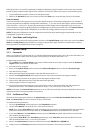
Bar Code Compatibility With Other Functions
Gang Count
Bar code operation functions fully with gang count. The scan data is attached to all cycles in the gang count. If Disable
tool until scan is selected via programming in the ICS software, the tool is disabled once the gang or assembly (see
Auto Increment) is complete. If a gang count needs to be reset, this must be performed through the Gang Reset Input
or the Run Main screen. On the Run Main screen, press 0 (zero) and then Enter. A re-scan of a part does not reset the
gang count.
Auto Increment
Auto increment operation functions fully when Disable tool until scan has been selected. In all cases both bar code
and auto increment will operate together. One bar code scan allows all Congurations in auto increment to operate
when in active mode. The scan should be set up to select the rst Conguration in the auto increment chain.
Powerhead
For the barcode function to be used with a powerhead, the powerhead must be created rst. Once the powerhead
has been created, set up bar code operation for spindle number 1 in the powerhead. The scan data is not added to all
spindles in the powerhead, only the lead.
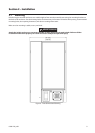
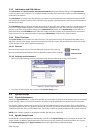
2.5 E-Stop Connection
The Emergency Stop (E-stop) feature allows for a rapid spindle shutdown (by the spindle user) in an emergency
situation.
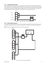
An emergency stop switch may be wired to the connectors provided at the bottom of the connector panel. An E-stop
for a single unit is connected to the controller’s internal 24V power supply. When multiple controllers are wired together
in a multiple-Conguration cabinet, an external power supply is used to run the E-stop so that the power for the entire
system is shut o when the E-stop is pressed.
E-stop is implemented via the Emergency Stop relay. The relay is normally energized. De-energizing it initiates E-stop.
The relay has two outputs: 1, 24 VDC which is used by the Motor Controller Electronics (MCE) for controlling other relays
that allow AC input voltage to be routed to the spindle’s bus voltage rectier and 2, a voltage signal that is routed to the
MCEs Control board processor to indicate that an emergency stop has occurred.
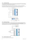
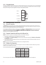
The E-stop relay coil terminals (+) and (-) are routed to jumper JP21 behind the I/O panel door. JP21 also has the
module’s internal 24 VDC power supply routed to it. The relay is energized by supply 24 VDC to the coil terminals at
JP21. The 24 VDC can be supplied by an external power supply or the internal 24-volt power supply.