04581740_ed2 19
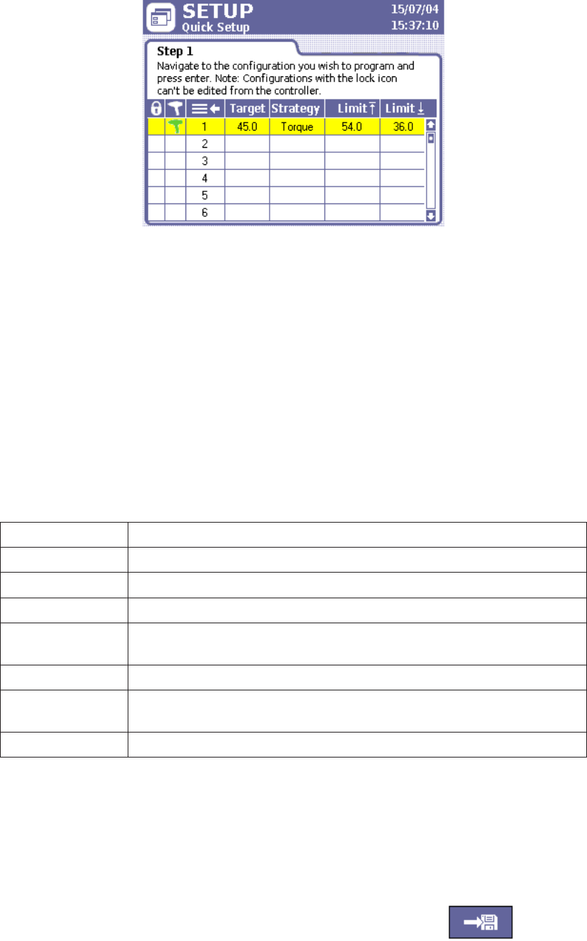
Figure 17 - Quick Setup Screen
To complete the parameters in the Quick Setup sub-menu:
1. Press the Setup menu button, then press Enter to choose the rst sub-menu, Quick Setup.
2. Use the arrow keys to move to one of the eight lines representing Congurations 1 through 8.
3. Press Enter to bring up the Step 2, the rst of two data entry screens used for setting up a Conguration.
4. Move to the Strategy parameter and select either Torque Control or Angle Control.
5. Select a direction CW (Clockwise) or CCW (Counter-clockwise).
6. Move to the next parameter on the screen and choose Torque Units: Nm, Ft-lbs, In-lbs, Kg-m, or dN.
7. Choose the button with the right arrow and press Enter to move to the second page of the Conguration setup process.
8. Using the numeric keypad, enter the desired target value for your fastening operation into the Torque Target or
Angle Target data entry box, depending on which of the two strategies you selected for a particular Conguration.
9. The Insight software automatically assigns values within target limits to the other torque or angle control
parameters displayed on this screen. If you want to edit any of these values, navigate to the data entry box and
enter a new value using the numeric keypad. These parameters include:
Torque High Limit The maximum acceptable torque value for a fastening.
Torque Low Limit The maximum acceptable torque value for a fastening.
Angle High Limit The maximum acceptable angle through which the fastener may turn.
Angle Low Limit The minimum angle through which the fastener must turn.
Torque Threshold
The torque required to seat components in the joint; also the torque point
at which angle begins to be measured.
Free Speed The maximum % speed the spindle can turn during fastening.
Shiftdown Point
The point during the nal stage of tightening at which the spindle shifts to
a lower speed to improve accuracy.
Shiftdown Speed The spindle % speed during the shiftdown phase.
10. If the assembly requires that multiple bolts are fastened in sequence, enter a Gang Count in the applicable data
entry box. See below for more information on Gang Count.
11. If you wish to setup the Insight to move through a specic sequence of fastening Congurations, use the Auto
Increment parameter. Enter the number of the Conguration you wish the Insight to use upon completion of the
current Conguration. See below for more information on Auto Increment.
12. Enter an Increment Reset parameter to indicate which Conguration the Insight should use after a Conguration
Reset Signal is received.
13. After you have completed entering all the parameters for your Conguration,
you must go to the Save button and hit Enter to store the settings you just
entered.
Save Button
Gang Count
Some assemblies have multiple bolts that must be fastened in sequence (called a “Gang”). For example, if you have a
four-bolt assembly you can set the Gang Count to 4. The controller then keeps track of each fastening and, when all four
fastenings have been completed within specication, a “Gang Complete” message appears on the display screen.


