


04581740_ed2 15
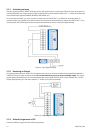
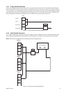
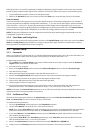
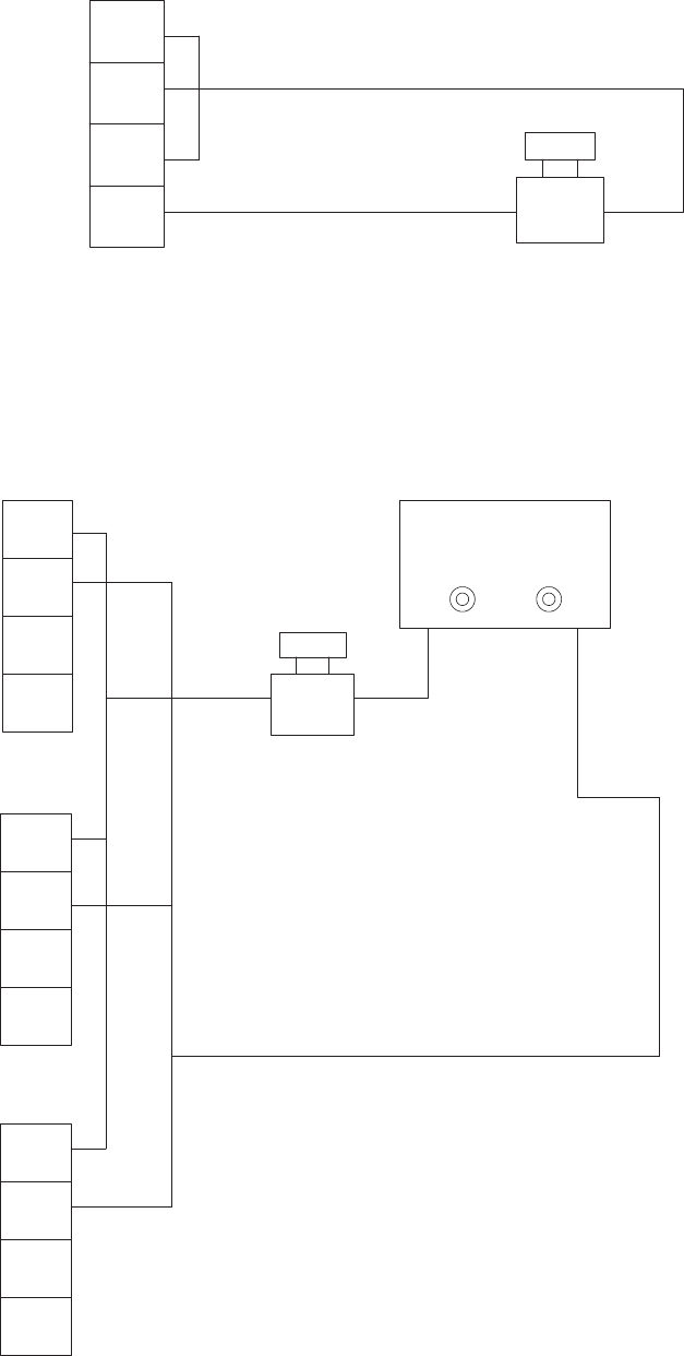
2.5.1 Single Spindle Operation
If the E-stop is being used, JP21 pin 2 (relay coil (-)) is routed to one contact of a remote (normally closed) SPST palm
button switch (PBS). The switch’s other contact is routed back to JP21 pin 4. JP21 pin 1 remains connected to JP21 pin
3. If an emergency occurs the spindle operator can depress the switch and the relay coil’s low side voltage path will be
interrupted. The E-stop can also be implemented by routing JP21 pins 1 and 3 to the remote switch. In this case, the
relay coil’s high side would be interrupted (JP21 pin 2 would have to be connected to JP21 pin 4).
Coil (+)
Coil (-)
Int 24V (+)
Int 24V Com
1
2
3
4
JP21
Figure 11 - E-Stop Connection, Single Spindle
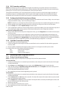
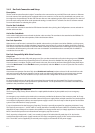
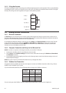
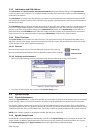
2.5.2 Multi-Spindle Operation
If an E-stop is being used, an external 24-volt power supply is used to energize each of the module’s Emergency Stop
relays. Depressing the PBS (Palm Button Switch) now interrupts the current ow to the E-stop relay on all modules.
NOTE: Each relay coil requires 25 mA (nominal) of power supply current.
1
2
3
4
JP21
Module 1
1
2
3
4
JP21
Module 2
1
2
3
4
JP21
Module n
24V
Power Supply
(+) (-)
PBS
Figure 12 - E-Stop Connection, Multi-Spindle