04581740_ed2 35
Test Data Element Explanation
Tool
Motor temperature Checks motor temperature and reports PASS or FAIL.
Amplier oset MCE’s oset voltage (as % of Shunt Cal voltage).
Shunt calibration Front-end electronics gain (as % of ideal Shunt Cal voltage).
Sine Oset The oset in A/D counts of the resolver sine analog input signal used for angle measurement.
Cosine Oset The oset in A/D counts of the resolver cosine analog input signal used for angle measurement.
Motor Kt The peak torque divided by peak current in the units of Nm/Amp.
Motor Control Electronics
MCE temperature Displays MCEs internal temperature.
Note that the System Test window is a display box.
To access and use System Test:
1. Press the Diag button on the Insight controller.
2. On the Diagnostics menu, select System Test and press Enter.
3. Scroll through the current measured values using the arrow keys.
4. Move the cursor to the Refresh button and press Enter to update the screen to the most recent readings.
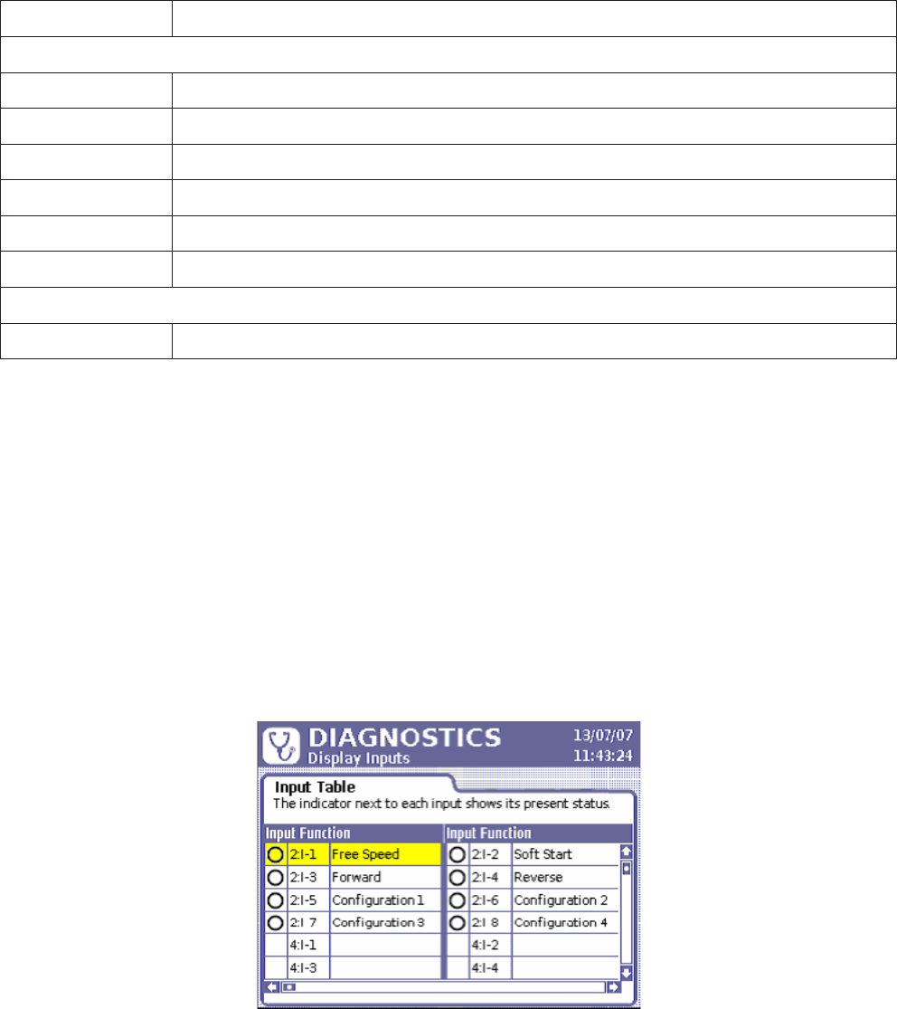
6.1.2 Display Inputs
The Display Inputs screen allows you to view the status of the Controller’s discrete inputs. I/O (Input/Output)
connectors are found on the left side panel of the Insight controller. Although the behavior of each input is
programmed in the ICS Software, this screen is useful for troubleshooting an I/O problem. For example, if the controller
was not running cycles started from a PLC, this screen would allow you to determine if the assigned input was
programmed and functioning properly. A green icon next to an input indicates that it is active, as shown in the example
screen below. If no signal is present, the circle remains white.
Figure 32 - Diagnostics Discrete Inputs Menu
To access and use Display Inputs:
1. Press the Diag button on the Insight controller.
2. On the Diagnostics menu, select Display Inputs and press Enter.
3. Scroll through the listed inputs using the arrow keys.
6.1.3 Set Outputs
With the Set Outputs screen, you can articially activate an output signal. This function is typically used for
troubleshooting; for example, you can send a signal to an external device (such as a PLC) to verify the device is
operating correctly. Unlike the Display Inputs screen, this screen does not have an indicator to represent a successful
output. The programmed function of each output is shown in the third column.


