04581740_ed2 21
3.3.3 Job Number and CAN Address
The Job Number and CAN (Controller Area Network) Address parameters found at the top of the System Setup
screen are used to set a Location ID for a particular Insight controller. The Location ID is used as a unique identier for
each unit on the network.
The Job Number is a 4-digit entry that represents a location on the assembly line. Each standalone Insight controller
has a unique job number. However, when controllers are arranged in a powerhead, each unit in the powerhead shares
the same job number.
The CAN Address reects whatever has been physically set on the unit’s rotary address switches. It should always read
0 (zero) for a single spindle operation. If it does not read zero, physically move the rotary switches on the unit until
they are set at 0.You cannot make a change to the CAN Address parameter on the System Setup screen itself. For a
powerhead setup, the CAN Address must reect the Insight controller’s position in the powerhead. See Powerhead
Setup on section 2.7 for more information on setting the CAN Address using the unit’s rotary switches.
3.3.4 Other Functions
The System Setup screen contains two other functions. The rst function consists of two buttons that allow you to
adjust the contrast of the display screen on the Insight controller up or down. The second function allows you to view
version numbers of the various software components.
3.3.4.1 Contrast
Move to the top button and press Enter to adjust the contrast of the screen up.
Move to the bottom button and press Enter to adjust the contrast of the screen up.
Contrast Up
Contrast Down
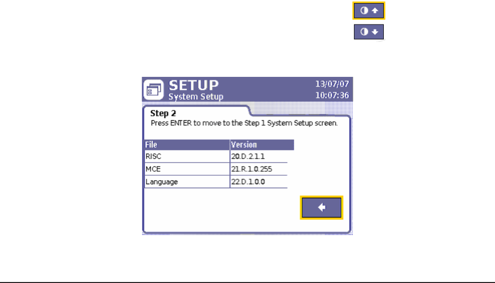
3.3.4.2 Software Version Numbers
1. Move to the right-pointing arrow key on System Setup and press Enter to go to Step 2 of the screen.
Figure 18 - System Setup, Step 2
2. Press Enter to return to the Step 1 portion of the System Setup screen.
3.4 Spindle Setup
3.4.1 Physical Attachment
Attach your Ingersoll Rand QE- or QM-series spindles (or powerheads) on the front of the Insight enclosure. At the end
of each spindle’s cable is a twist-to-lock multi-pin connector. Plug the spindle into the connector and lock it in place.
If no spindle is present, when the unit is powered up, no power is delivered to the empty connector. This is a safety feature.
The Insight interprets the lack of a spindle as a spindle with a possible ground fault, and does not energize that circuit. To add
a spindle at a later time, rst turn o the Main Power Switch. Next, connect the spindle, wait ve seconds, and turn it back on.
NOTE: Never connect a spindle to the Insight Controller with the power switch ON.
3.4.2 Spindle Setup Screen
Notice that the connected spindle’s model number is shown on the Spindle Setup screen, just below the header. The
screen contains ten dierent spindle parameters that can be set. It also contains two buttons that allow you to return
the Transducer Range and the Angle Constant values to the original factory-calibrated settings.


