8 04581740_ed2
1.1.5 Using Menus and Screens
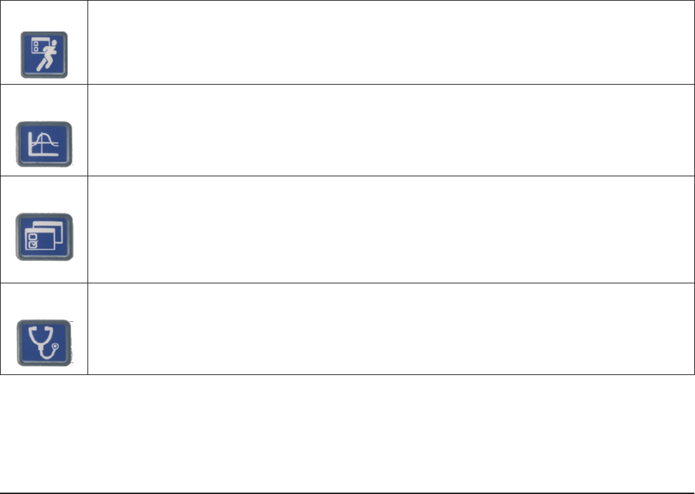
1. Push the corresponding button to select the menu section you want to view. There are four sets of menu screens
from which you can select. The selection buttons for these four menus are located above the display screen in the
upper part of the front panel.
Run
The Run screen displays fastening data (torque and angle after each fastening operation.
Statistics
The Statistics menu displays raw fastening data as well as statistical analyses. Statistics consists of
four sub-menus. The rst sub-menu, Cycle Log allows viewing of previously recorded tightening
data. Other sub-menus include Spindle Stats, Powerhead Stats, and Stats Settings, which provides
general statistics parameters.
Setup The Setup menu programs the fastening strategy. The ve sub-menus on Setup include a Quick
Setup feature that allows rapid programming of standard strategies, while System Setup contains
settings for general parameters such as date and time. Setup also controls numerous basic system
parameters, such as the Spindle Setup sub-menu, which is used to select spindle parameters, and
Serial Setup and Ethernet Setup, which are used to set the respective port parameters. The PLUS
Settings submenu will be available for those customers using the PLUS communications protocol.
Diagnostics
The Diagnostics menu controls Insight’s self-diagnosis programs. Insight continually looks for
operating problems or component failures. It alerts the operator to problems with the spindles or with
the controller electronics, and can even suggest root causes and corrective action.
2. To choose a sub-menu from a selected menu, use the cursor (arrow) keys to highlight (select) a sub-menu item and
then press the Enter key to start that item. You can also select the sub-menu by pressing the number associated
with that menu. There are up to ve sub-menu options for each menu type.
3. To enter numeric data into a eld, simply highlight the desired onscreen element, use the numeric keypad to enter
numbers and press the Enter key.
1.2 System Options
1.2.1 Field Bus
Your system may come equipped with a eldbus slave card. The eld buses allow the Insight unit to communicate with
other devices across a network. Supported cards are:
• Probus
• DeviceNet
• Modbus RTU
• Interbus S
• Ethernet IP/Modbus TCP
1.2.2 Expanded I/O
The base unit is equipped with eight discrete inputs and eight outputs for connection to peripheral devices. The Insight
accommodates an optional remote I/O board with an additional 16 inputs and 16 outputs, totaling 24 inputs and 24
outputs. The input/output functions are fully assignable and programmable using ICS Software.
1.2.3 Cabinet Mounting
The Insight comes standard with wall-mounting brackets. An optional cabinet-mounting bracket is available that allows
the heat-sink ns to extend out of the back of the cabinet. Use the bracket as a template to cut a hole through the back
of the cabinet in the position where you wish to place the unit. Install the cabinet mounting bracket after rst removing
the wall-mounting brackets from the unit.
