


A-6
INSTALLATION
MAXsa™ 22 & 29 WIRE DRIVES
A-6
POWER WAVE
®
AC/DC 1000 SD SUBARC
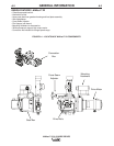
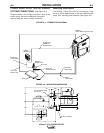
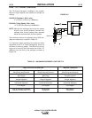
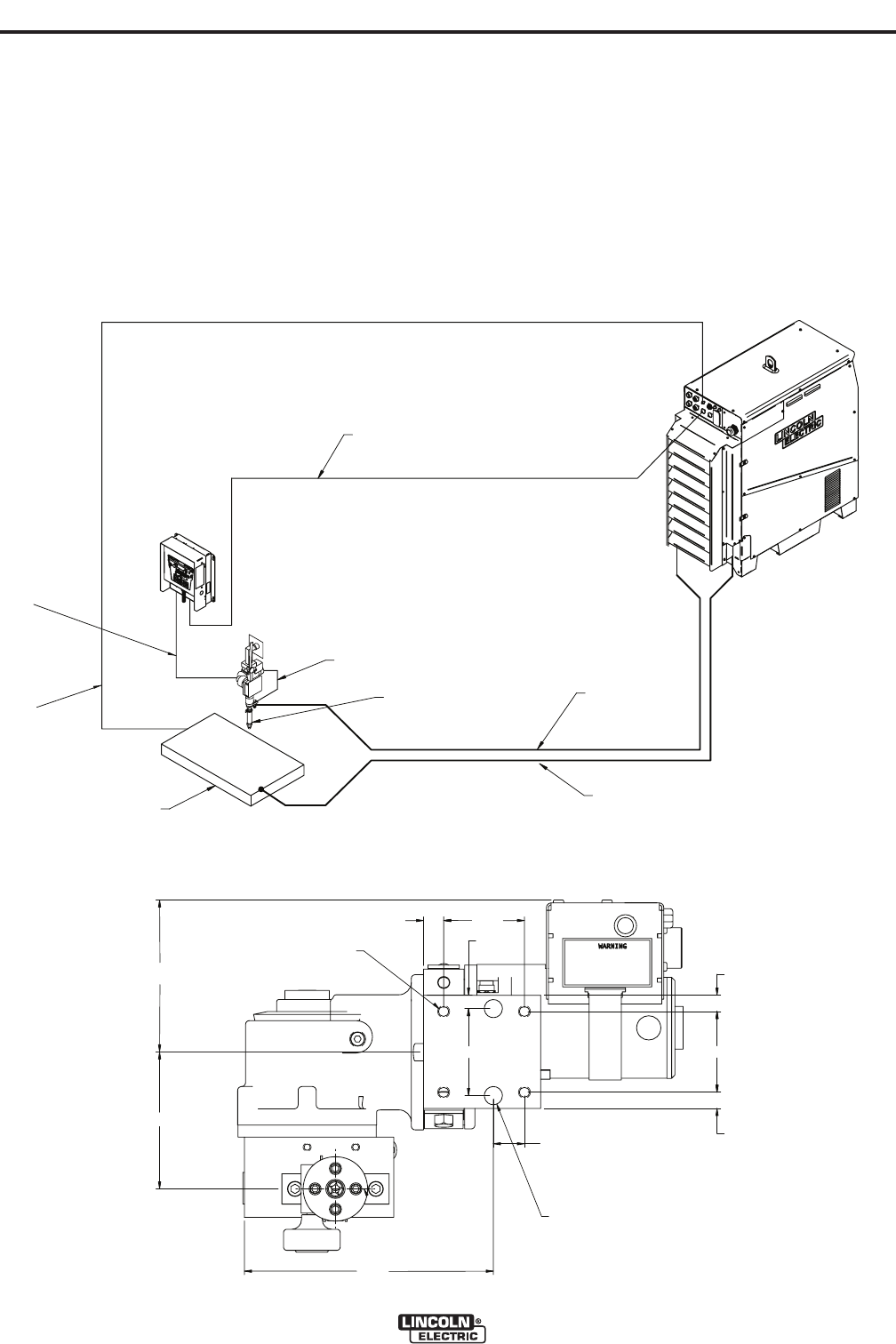
SYSTEM CONNECTIONS (
See Figure A.3)
Diagram shown is for a single arc system. Refer to the
power source manual for additional connection
options (Multi-arc and/or parallel machines).
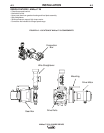
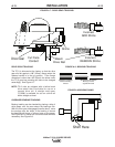
Mounting Dimensions
The MAXsa™ Wire Drive can be mounted by using
the four 3/8-16 tapped holes or the two 0.562 through
holes. See mounting hole locations (See Figure A.4).
FIGURE A.3 - CONNECTION DIAGRAM
FIGURE A.4 - MOUNTING DIMENSIONS
K2683-XX
Arclink Cable
67 Lead
K1795-XX
14-Pin Cable
Work
K231-XX
Contact Nozzle
K
2803-1
Power Wave
® AC/DC 1000
K2814-1
MAXsa™ 10
K2370-2
MAXsa™ 22
K1811-XX
Sense Lead
Electrode
Weld Cable
Work
Weld Cable
K1543-XX or
7.70
4.70
4.24
.62 2.50
.41
2.69
.96
.50
2.50
.50
.562 (2 HOLES)
3/8-16 TAPPED HOLE
(4 PLACES)
ø