


C-7
ACCESSORIES
MAXsa™ 22 & 29 WIRE DRIVES
C-7
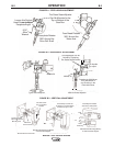
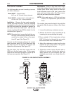
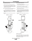
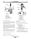
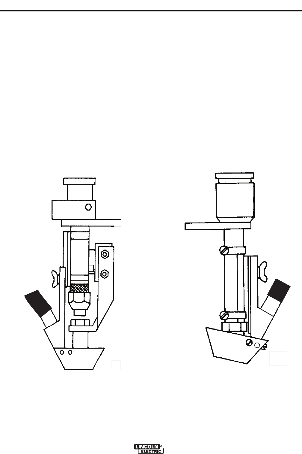
K285 Installation with K149
1. Install the K149 to the K148 per the instructions.
2. Loosen the hose clamps of the K285 entirely, place
them around the nozzle and tighten them so that
the stationary part of the K285 is directly opposite
the K149 arm. See Figure C.10
NOTE: The lower hose clamp must be positioned so it
does not touch the arm of the K149.
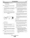
4. Position the moveable section to the desired flux
height and tighten the wing nut. Use the center or
lower tapped hole depending on the electrical
stickout
5. Cut the flux hose to required length and connect as
shown.
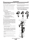
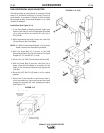
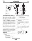
K285 installation with the K129
1. Unscrew the hose clamps enough so they can slip
over the tip holder clamping nut.
2. Position the stationary portion of the K285 as
shown in Figure C.11 and tighten the clamps.
3. Position the moveable section to the desired flux
height and tighten the wing nut.
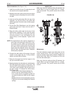
4. Due to the 7° angle of the tips it may be necessary
to pivot the cone as shown. Remove the outermost
screws from each side of the cone. tilt the cone
and put the two screws into the rear of the cone.
Tighten all 4 screws.
5. Cut the flux hose to required length and connect as
shown.
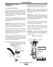
IMPORTANT
K285 on ALL Nozzles
After the K285 is installed to any of the compatible
nozzles, use an ohmmeter or a test light to insure
proper insulation (no continuity) between the copper
flux cone and the nozzle body
FIGURE C.10 - K285/K149
FIGURE C.11 - K285/K129