


B-2
OPERATION
B-2
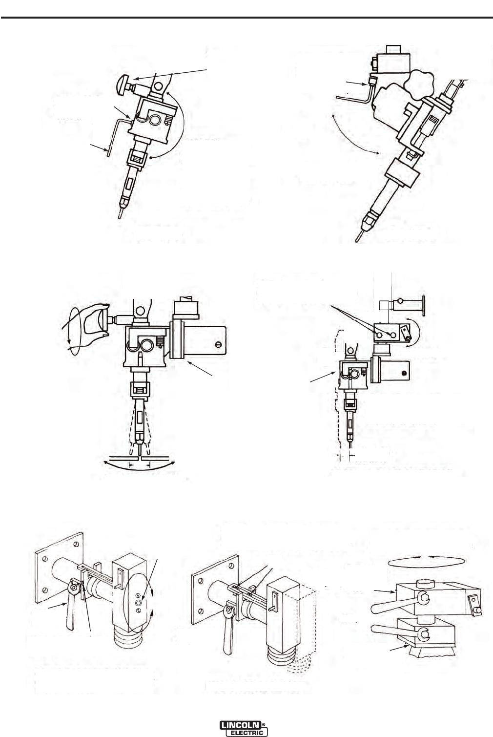
MAXSA™ 22 & 29 WIRE DRIVES
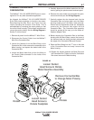
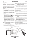
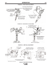
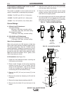
FIGURE B.2 - HORIZONTAL ADJUSTMENT
This Adjustment Can be
Locked by Tightening
Two Socket Head Screws
Rotating the K96 Allows
for 2” Movement in
any Direction in the
Horizontal Plane
Turn Handle
to adjust
Cross Seam Adjuster
K96 Horizontal Adjuster
MAXsa 29
MAXsa 22
2 1/2”
2
”
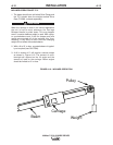
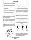
FIGURE B.1 - FEED HEAD ADJUSTMENT
Loosen this Socket
Head Screw to Adjust
Faceplate Angle
5/16”
Allen
Wrench
Face-plate Rotates
360° Around the
Drive Roll Shaft
Feed Head Rotates
360° Around the
Motor Axis
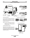
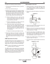
T
he Cross Seam Adjuster
Can Be Mounted to the
Top or Bottom of the
Gear Box
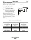
FIGURE B.3 - VERTICAL ADJUSTMENT
With Standard Mounting (M6767)
or K29 Vertical Adjuster
Loosen to Rotate
Entire Head Around
Mounting Axis
With K29
Loosen Screw
K29 Clamps Can Be Set
to Restrict In and Out Motion
to Distances up to 3 3/4”
Head May Be Rotated
Around the Vertical Axis
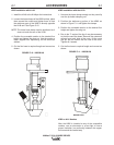
K96
Head
Mounting
With Standard Mounting (M6767)
or K96 Horizontal Adjuster
Use This Screw
To Lock Vertical
Position