


C-4
ACCESSORIES
C-4
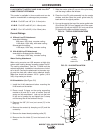
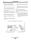
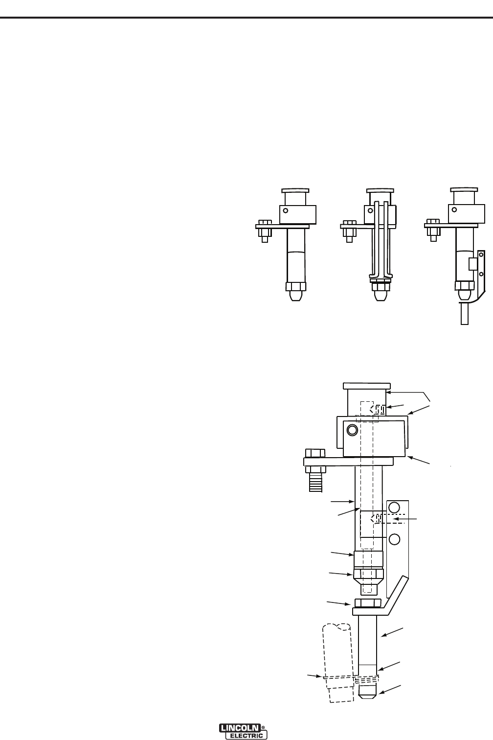
K148 CONTACT NOZZLE AND K149 Linc-Fill
TM
LONG STICKOUT EXTENSION
This nozzle is available in three models and can be
used for Innershield® or submerged arc processes.
K148-A - For 3/32” and 1/8” (2.4 - 3.2mm) wire.
K148-B - For 5/32” and3/16” (4.0 - 4.8mm) wire.
K148-C - For 1/16” to 5/64” (1.6 to 2.0mm) wire.
Current Ratings
A. Without Linc-Fill Attachment
Innershield Welding:
600 amps, 100% duty, no water cooling
1100 amps, 100% duty, with water cooling
Submerged arc welding:
1100 amps, 100% duty, no water cooling
B. With K149 Line-Fill Attachment
Innershield or Submerged Arc Welding:
1100 amps, 100% duty, no water cooling
Water Cooling Attachment
When using currents over 600 amperes at high duty
cycles water cooling always increases contact tip life.
The cooling attachment, Part No. T12928 must be
ordered seperately. Installation instructions are includ-
ed in the kit. Connect the attachment to the water sup-
ply and the drain with rubber tubing obtained locally.
Water flow should be between 1/2 to 1 gallon (1.9 to
3.8L) of tap water per minute.
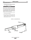
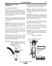
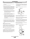
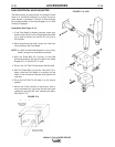
K149 Installation (See Figure C.5)
1. Install the K149 attachment before mounting the
K148 nozzle on the welder.
2. Place a small C-clamp on the spring supporting
members (A) and (B) in such a manner that the
spring can be compressed. Look up into the hole
in the end of contact tip and tighten the C-clamp
until the tang lifts off the surface of the tip.
3. Remove the 3/8” (9.5 mm) set screw (C) in the
body (A).
4. Remove the contact tip clamping nut (D) and the
contact tip.
5. Remove the brass thread protecting collar (E).
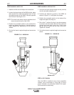
6. Remove the dirt shield (F) from the barrel of the
nozzle.
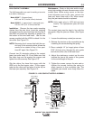
7. Slide the center guide (G) up out of the pivot body
until the tang is above the window.
8. Place the Linc-Fill guide assembly into the nozzle
window, and then lower the center guide tube (G)
back down to its original position.
9. Line up the spot at the top of the center guide tube
(G) with the 3/8” (9.5 mm) tapped hole in the upper
pivot block (A) and put the 3/8” (9.5 mm) set screw
(C) back into the hole and tighten securely.
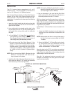
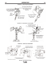
MAXSA™ 22 & 29 WIRE DRIVES
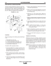
FIG. C.4 - TYPICAL CONFIGURATIONS
K 148 & K 149
K 148
With Water
Cooling
Attachment
K 148
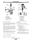
FIG. C.5 - K149 INSTALLATION
A
B
F
G
E
D
11
10
12
13
14
C
H