


A-11
INSTALLATION
MAXsa™ 22 & 29 WIRE DRIVES
A-11
INSTALLATION
The TC-3 comes factory assembled to fit an 8”
(203mm) beam. See print G1458 for instructions to
use it on 10” (254mm) or 12” (305mm) beams.
The Carriage Release Handle, the Wire Reel Support
Bracket and the Wire Drive Support Bracket are not
factory mounted. They should be mounted to the car-
riage before it is placed on the beam per the following
instructions.
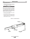
1. Insert the clutch handle into the hole on the right
side of the carriage so that the end of the handle is
goes into the lift yoke.
2. Line up the hole in the handle and the hole in the
lift yoke and insert the roll pin that came taped to
the handle. Drive in the roll pin until it is flush with
the yoke.
3. a. If the MAXsa™ 10 Control Box is not
going to
be mounted on the carriage, mount the Wire
Reel Support Bracket to the left front corner of
the carriage using the hardware provided.
b. Do not mount the Wire Reel Support if the
K2462-1 Control Box Mounting Bracket for the
MAXsa™ 10 is to be mounted on the carriage.
Another means of mounting the wire must be
used such as a K390 or a user supplied support
for a K299 or K162-1 Spindle Kit (ordered sepa-
rately).
NOTE: Do not mount the K2462-1 Bracket for the
MAXsa™ 10 Control Box until after the car-
riage is placed on the beam.
4. Install the Wire Drive Mounting Bracket that is sup-
plied with the MAXsa™ 22, using the hardware
and insulators provided. See Figure A.6.
NOTE: To install a MAXsa™ 29 Wire Drive order a
Mounting Bracket (M6769) and the appropri-
ate Head Support (K29 or M8232).
5. Use an ohmmeter to be sure that the Wire Reel
shaft and the Wire Drive Mounting Bracket are
electrically isolated from the TC-3 frame.
With the release handle all the way down, set the car-
riage on the beam. It should run freely along the
beam. With the release handle in the up position the
drive gear should engage the track and hold the car-
riage securley in position.
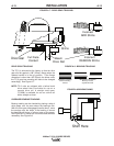
If the MAXsa™ 10 Control Box is to be mounted to the
TC-3:
1. Attach the K2462-1 bracket to the left side of the
carriage per the instructions included with the
bracket.
NOTE: Make certain that there is enough clearance to
the left of the beam to accomodate the K2462-
1 bracket
2. Mount the MAXsa™ 10 Control Box to the brack-
et and connect the 4 pin connector from the
Travel Control to the mating receptacle on the
bottom of the MAXsa™ 10 Control Box.
Keep the load on the TC-3 as uniform as practical.
Install cables so that they move smoothly with the car-
riage. Clamp the weld cables to the carriage using the
cable clamp on the left rear corner.
After all of the equipment has been mounted to the
carriage, the tracking of the drive gear and the bear-
ings should be checked.
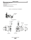
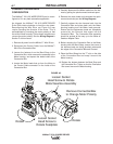
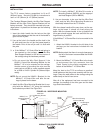
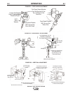
FIGURE A.6 - WIRE DRIVE MOUNTING
Wire Reel
Mounting Bracket
Clutch
Handle
Wire Drive Mounting
Bracket (M6769)
Head Support
(M8232)
MAXsa™ 10
Mounting Bracket
(K2462-1)