


A-13
INSTALLATION
MAXsa™ 22 & 29 WIRE DRIVES
A-13
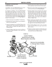
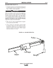
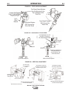
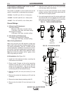
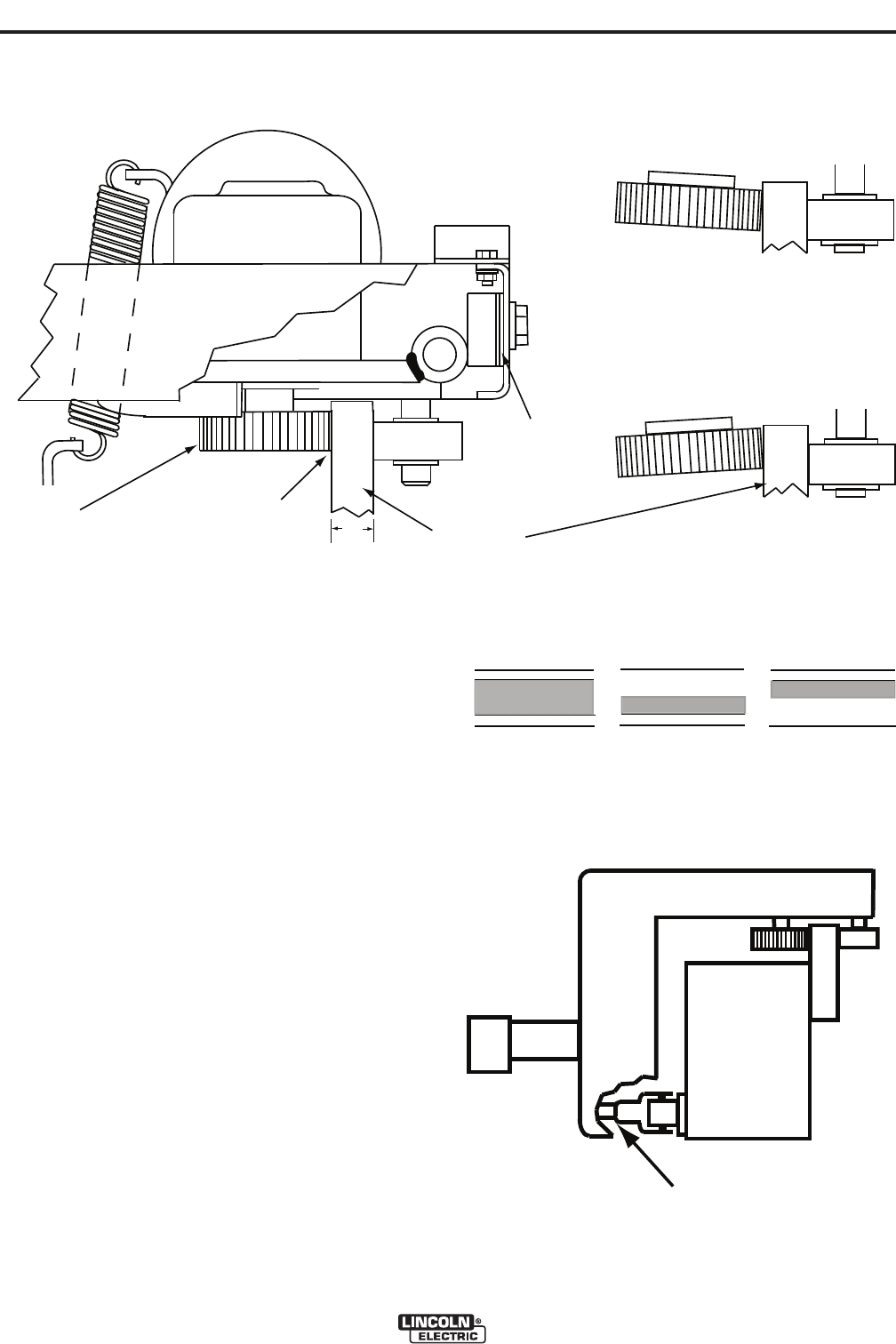
FIGURE A.8 - BEARING TRACKING
INCORRECT PATTERNS
Bearing is not flat
Against Drive Rail
CORRECT PATTERN
Full Face Bearing
Contact
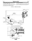
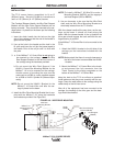
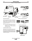
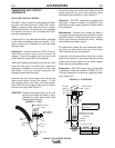
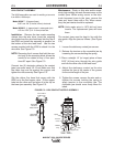
FIGURE A.7 - DRIVE GEAR TRACKING
Beam
Drive Rail
Shims
Full Face
Contact
Drive Gear
Incorrect
ADD Shims
Incorrect
REMOVE Shims
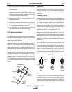
.88”
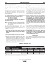
FIGURE A.9 BEARING SHIMS
Shim Here
DRIVE GEAR TRACKING
The TC-3 is shimmed at the factory so that the drive
gear sits flat against a .88” (22mm) flange when the
release handle is in the up position. If the flange
dimension is other than .88” (22mm) the shims under
the TC-3 gear box mounting will have to be changed
accordingly. See Figure A.7.
NOTE: TC-3 units are shipped with a helical tooth
drive wheel that is suitable for use on a
smooth drive rail. A straight tooth gear
(T13586) is available for use on a drive rail
with a straight cut knurl.
CARRIAGE BEARING TRACKING
Bearing tracking can be checked by placing a strip of
white paper over the area where the bearings ride.
With the drive gear disengaged (handle down), move
the carriage over the strips. If the tracking is correct
the bearings will leave a uniform trace on the paper.
See Figure A.8. If traces are not corrrect add shims as
necessary. See Figure A.9.