


B-1
OPERATION
B-1
ROUTINE OPERATION
Once the procedures and parameters are properly set
at the controller the operator should be able to make
production welds without changing those settings. A
typical weld sequence is as follows:
1. Before starting, make sure that:
a. There is enough wire on the reel(s) to finish
the weld.
b. The flux hopper is filled with new or proper-
ly screened flux.
2. Energize the power source and wait for it to stabi-
lize (all Status LEDʼs Green).
3. Position the Wire Feed Head at the start of the
weld. Be sure the TC-3 Carriage or travel mecha-
nism is set to move in the proper direction
4. Set the travel switch for “Automatic Travel” if the
“Hand Travel” position was used to position the
feed head in Step 3.
STARTING TECHNIQUES
1. Hot Starting - refers to starting the weld with the
Wire Drive head stationary and the wire not touch-
ing the workpiece.
a. Always cut the end of the wire to a sharp
point.
b. Press Feed Forward until the wire touches
the work piece and the flux hopper acti-
vates to put flux around the starting point.
c. Press Feed Reverse to retract the wire 1/8”
to 1/4” (3.2-6.4mm).
d. Use the Set-Up menu of the MAXsa™ 10
or remote controller to determine whether
the travel will begin with Start Button
pressed or with weld current (preferred).
e. Press the START button to initiate the weld.
f. Press the STOP button to begin the stop-
ping sequence.
h. If necessary, press the Feed Reverse to
move the electrode out of the way.
2. On-the-fly Starting - refers to starting the weld
after the travel begins to get a “scratch” start.
Normally this type of starting requires the use of a
ʻrun-onʼ tab to insure proper weld deposition at the
beginning of the weld.
a. Use the Set-Up Menue of the MAXsa™ 10
to set the travel to start with the START
button.
b. Follow the Hot Starting procedure.
Cold Starting - refers to starting the weld with the
Wire Drive Head stationary and the electrode touching
the work.
a. This procedure is not recommended for the
Power Wave® AC/DC 1000 / MAXsa™ 22
& 29 WIRE DRIVES combinations but may
work OK with smaller diameter wires and
proper setting of the Start parameters.
b. Follow Hot Starting procedure but omit
“step c”.
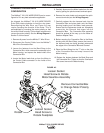
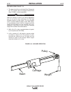
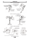
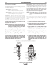
HEAD POSITION ADJUSTMENTS
The MAXsa™ 22 & 29 WIRE DRIVES can be easily
adjusted to any weld position. The most often used
adjustments are available on both the MAXsa™ 22
and the MAXsa™ 29 Wire drives. See Figure B.1
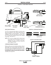
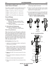
Turn the Cross Seam Adjuster (MAXsa™ 29) to keep
the arc in the joint as necessary. With a MAXsa™ 22,
a K96 or some other means of horizontal adjustment
is recommended. See Figure B.2
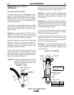
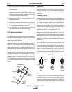
The entire Wire Drive can be moved into or out of the
Mounting Bracket (M6789). If using a K29 Vertical Lift
Adjuster it can be locked in either the horizontal or
vertical position once the vertical position is set. See
Figure B.3.
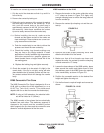
If the Wire Drive is rotated to a position where the
faceplate is upside down, the contact nozzle and the
wire straightner and guide tubes will need to be
reversed. The polarity of the motor will also need to be
changed so the wire feeds in the proper direction. See
the Installation Section, Changing the Wire Drive
Configuration for instructions on changing the motor
polarity.
MAXSA™ 22 & 29 WIRE DRIVES