


A-9
INSTALLATION
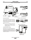
MAXsa™ 22 & 29 WIRE DRIVES
A-9
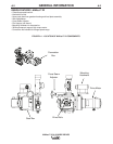
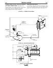
ELECTRODE CONNECTIONS
Because the Power Wave® AC/DC 1000 SD can pro-
duce either a DC positive, DC negative or AC output the
electrode and work connections do not need to be
reversed for the different polarities. Additionally no DIP
switch changes are required to switch between the dif-
ferent polarities. All of this is controlled internally by the
Power Wave® AC/DC. The following directions apply to
all polarities:
Connect the electrode cable(s) to the "ELECTRODE"
stud(s) on the power source . Connect the other to the
contact assembly at the Wire Drive. Be sure the con-
nection makes tight metal-to-metal electrical contact.
The electrode cable should be sized according to the
specifications given in Table A.1.
NOTE: On the Power Wave® 1000 SD, the Electrode
studs are on the lower left rear corner of the
machine. On older units they are on the lower
left front corner. On those machines,
the
cables can be routed through the oval hole in
the cable tray before being connected to the
output terminals.
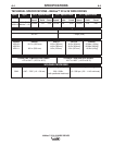
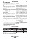
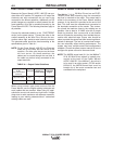
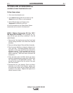
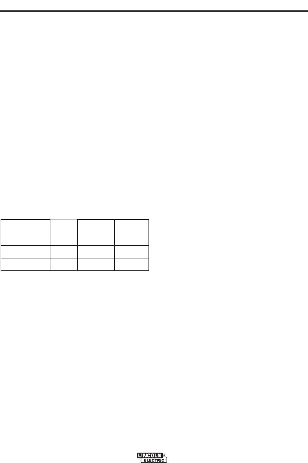
TABLE A.1 - Output Cable Guidelines
When using inverter type power sources like the
Power Wave®, use the largest welding (electrode and
work) cables that are practical. When using AC appli-
cations the current can reach very high levels. Voltage
drops due to cable resistance can become excessive,
leading to poor welding characteristics if undersized
welding cables are used.
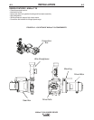
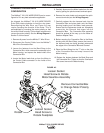
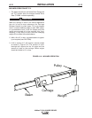
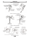
REMOTE SENSE LEAD SPECIFICATIONS
The MAXsa™ 22 & 29 Wire Drives has an ELEC-
TRODE sense lead extending from the connection
box that is mounted to the motor. This sense lead is
critical to the accuracy of the Power Wave® welding
process. A ring terminal is provided at the end of the
lead. This lead must be extended and connected to
the electrode connection at the nozzle. This connec-
tion should be made as close to the welding arc as
possible. Use at least a 12 AWG wire with a proper
sized ring terminal. Use a screw with a lock washer
and nut to make the connection, then insulate the con-
nection with electrical tape. Proper care should be
taken to protect the sense lead from becoming discon-
nected or damaged. The loss of a sense lead connec-
tion can adversely affect welding performance. The
system may have multiple sense lead configurations
available. Consult the power source manual on how to
configure the power source for the sense leads.
NOTE: The WORK sense lead (21) for the MAXsa™
22 & 29 Wire Drives system is typically con-
nected at the back of the Power Wave®
AC/DC 1000 SD. If the MAXsa™ wire drive is
to be used in an older system, (PF10A and/or
K2344-X) the WORK sense lead must be
brought out of the motor connection box and
connected to the workpiece.
Total Cable Length
ft (m)
Electrode and Work
Combined
0 (0) to 250 (76.2)
0 (0) to 250 (76.2)
Duty Cycle
80%
100%
Number of
Parallel Cables
2
3
Cable Size
Copper
4/0 (120 mm
2
)
3/0 (95 mm
2
)