


A-8
INSTALLATION
MAXsa™ 22 & 29 WIRE DRIVES
A-8
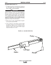
WIRE FEED MECHANISM
All MAXsa™ Wire Drive units are shipped with 142:1
ratio gears. Conversion kits are included to change to
either 95:1 or 57:1 ratio depending on wire size to be
used.
As shipped, the drive mechanism parts are designed to
feed 3/32 through 7/32(2.4mm - 6.0mm) wire. Other
wire sizes will require different drive rolls and guide
tubes. See table A.1.
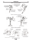
The Idle Roll pressure will need to be adjusted for the
wire being used. The indicator shows two settings -
.035 - 3/32” (0.9 - 2.4mm)
.120.- 7/32” (3.0 - 6.0mm)
The tension adjustment is to be made after loading the
wire into the drive rolls.
NOTE: Lower tension may need to be needed to pre-
vent crushing of some cored wires or softer
alloy solid wires.
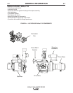
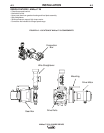
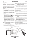
GEAR RATIO CONVERSION KITS (See
instruction sheet included with the conversion kit
for graphic illustration.)
1. Remove the 2 hex head screws and the 2 slot head
screws holding the Motor to the Wire Drive Gearbox
assembly.
2. Remove existing Adapter Plate and Motor Assembly.
3. Take the two long screws removed in step 1 and
screw one into each of the tapped holes located on
the face of fiber input helical gear. Insert the screws
through the full thickness of the gear, and using a
screwdriver wedged between the screws to prevent
rotation, remove the hex nut that holds the gear to
the shaft. Remove plain washer.
4. Pull the gear from the shaft using the screws as a
pulling device.
5. Be certain woodruff key is properly located on the
shaft. Screw the adapter plate and motor assembly
mounting screws into the new fiber input helical
gear from the stenciled side and place the gear on
the shaft. Replace plain washer, tighten the hex
nut, and remove the adapter plate and motor
assembly mounting screws from the gear.
6. Support the pinion properly and, with the proper
size punch, drive the roll pin that holds the pinion
out of the shaft. Pull the pinion off. Remove the
Ring Magnet from the pinion gear and snap it onto
the new pinion gear. Before installing the new pin-
ion gear with the Ring Magnet onto the motor shaft,
ensure that the flat washer is located at the bottom
of the shaft. Install the new pinion and replace the
roll pin.
7. Cover the teeth of the motor pinion and the input
gear with a non-fluid molydisulfide type grease such
as Non-Fluid Oil Corporationʼs A-29 Special/MS
Lubricant. This grease can be scooped from the
cavity of the gear case.
8. Reassemble the motor to the gearbox. Make sure
the gears mesh properly and the adapter plate
locating bead is in its cavity. Replace and tighten
the four screws removed in step 1.
IMPORTANT
See the MAXsa™ 10, or power source manual for
instructions on configuring the system for the
new gear ratio.
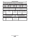
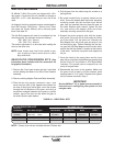
TABLE A.1 - DRIVE ROLL KITS
Drive Roll Drive Roll Incoming Outgoing
Kit Number Wire Sizes & Types Part Number No. required Guide Guide
KP1899-1 3/32-7/32” Wires KP1885-1 2 KP2116-2 KP1963-1
KP1899-2 1/16-3/32” Wires KP1886-1 2 KP2116-1 KP2097-2
KP1899-3 .035-.052” Solid Wire KP1887-1 1 KP1967-1 KP2097-1
KP1899-4 .045-.052” Cored Wire KP1892-1 2 KP1967-1 KP2097-1
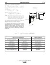
KP1899 DRIVE ROLL KIT
INCLUDED WITH KIT
NOTE: Twinarc drive rolls are included with the ATwinarc kits.