


C-14
ACCESSORIES
MAXsa™ 22 & 29 WIRE DRIVES
C-14
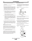
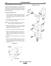
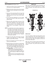
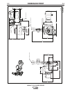
Nozzle Installation (See Figure C.18)
1. install the new idle roll arm (C) using the pin and
set screw from the original assembly.
2. Replace the tension spring and screw and adjust
the tension screw to the proper line on the indica-
tor plate.
3. Insert one of the guide tubes (B) in the top of the
faceplate. Line up the holes in the guide tube
with the grooves in the drive rolls to insure proper
wire feed
4. Put the Dual Wire Straightener over the ingoing
guide tube and lock it down with the two “L”
shaped clamps
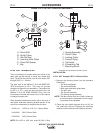
5. Place the other guide tube into the top of the
K225 Nozzle Assembly (F) and slide the guide
tube into the Wire Drive faceplate until the
mounting screws (1) can be started into the
tapped holes in the faceplate. Tighten both
screws.
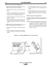
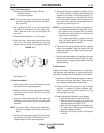
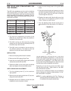
NOTE: For applications that require staggered or
cross seam wire placement rather than in-line,
the nozzle can be rotated by loosening the
two1/4-20 socket head screws (9) that hold
the nozzle to the mounting base. If the desired
angle cannot be obtained, remove the screws
and put them into alternate holes. Retighten
when properly adjusted.
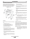
6. Connect the weld cables of the proper size and
number to the copper bar (2). If using multiple
cables, use both sides of the bar.
7. Route the flux hose from the flux hopper to the
clip (3) on the K225 nozzle.
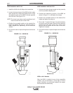
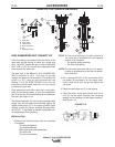
8. Spacing between the electrodes is maintained by
the center block which comes in three sizes. The
.50 “ and .625” center blocks come with the kit. A
.375” block is also available. See the parts list for
the part number. To change the center block,
See Figure A-30:
• Loosen both of the Pressure Springs (5)
• Remove the two Socket Head Screws (7)
• Put a small amount of graphite grease on
the screw threads and install the new copper
block.
• Replace the two screws and tighten securely
• Tighten the four screws holding the Pressure
springs
IMPORTANT
Make sure that the mating surface (8) between the
Center Block (4) and the Copper Bar (2). is bright,
clean and smooth. This junction carries the full weld
current.
Maintenance
The most extensive contact wear takes place on the
center contact block. The side pressure jaws are
made of a harder longer lasting material. Replace the
center block when there is no pressure on the wire
from the side contact jaws.
Make sure that the mating surface (8) between the
Center Block (4) and the Copper Bar (2). is bright,
clean and smooth. This junction carries the full weld
current.
FIGURE C.20
1
2
7
5
9
6
4
3
8