


C-12
ACCESSORIES
MAXsa™ 22 & 29 WIRE DRIVES
C-12
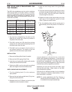
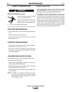
B. For 3/32 (2.4mm) Wire
1. Remove the items listed in Step “A” plus:
• The drive roll key
• The drive roll spacer
NOTE: The set screw that holds the drive roll spacer
in place is accessible once the idle roll assem-
bly is removed.
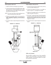
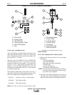
2. Oil or grease the O.D. of the new shorter drive
roll spacer (E) and place it on the output shaft.
Push it back as far as it will go and tighten the
set screw.
3. Place the new longer key (F) in the keyway.
4. Place the outer, center and second outer drive
rolls (A) on the shaft. Replace the clamping
washer and the locking nut and tighten securely.
See Figure C.17.
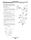
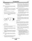
C. Nozzle Installation
1. install the new idle roll arm (C) using the pin and
set screw from the original assembly. .
2. Replace the tension spring and screw and adjust
the tension screw to the .045-3/32 line on the
indicator plate.
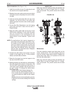
3. Insert one of the guide tubes (B) in the top of the
faceplate. Line up the holes in the guide tube
with the grooves in the drive rolls to insure proper
wire feed
NOTE: If using the K281 Twinarc Wire straightener,
follow the supplied instructions and skip to
Step 5.
4. Put the dual ingoing wire guide (D) over the ingo-
ing guide tube and lock it down with the two “L”
shaped clamps from the wire straightener.
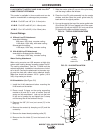
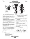
5. Insert the two long insulated wire guides (2) into
the Twinarc nozzle (1) making sure that they are
seated in the holes in the mounting block (7).
Place the contact tip (4) or tip holder (5) into the
end of the nozzle making sure the tubes fit into
the holes. Lock it securely in place with the lock-
ing collar (3). See Figure C.16.
NOTE: For applications that require staggered or
cross seam wire placement rather than in-line,
the contact tip or tip holder may be rotated.
Re-adjust the head position to maintain the
proper wire-to-work angle.
For overlay applications a special “side by
side” tip holder (part# S17728) that accepts
standard contact tips is available.
6. Place the other guide tube (B) into the outgoing
side of the faceplate. Place the nozzle over the
guide tube and lock it in place with the two sock-
et head screws
7. Bolt the electrode cable(s) of the proper size and
number, to the connection tab (6) using the hard-
ware provided. If using multiple cables, use both
sides of the tab.
E. Maintenance
Replace the Contact Tip(s) when they no longer pro-
vide accurate wire placement or good electrical con-
tact. Before installing the new contact tip or tip holder:
1. Make sure that the threads and bottom surface of
the nozzle are clean and bright. These are cur-
rent carrying surfaces and must be clean.
2. Check that the locking collar is free of foriegn
material. A coating of locally available “anti-
seize” compound or graphite grease will help
insure longer thread life.
3. Before replacing the contact tip or tip holder:
a. Inch the wire past the end of the nozzle.
b. Slide the long wire guides on to the wire
making sure they are properly seated in the
mounting block (see Figure C.16).
c. Slide the new contact tip or tip holder over
the wires again making sure that thewire
guides are properly seated
d. Replace the locking collar and tighten
securely
FIGURE C.17
O
utput
Shaft
Drive Roll
Spacer
Key Outer Drive Rolls
C
enter
D
rive Roll
Clamping
Washer
Locking
Nut