C-5
ACCESSORIES
C-5
10. Line up the lower spot in the center guide tube (G)
with the 3/8” (9.5 mm) set screw (H) and tighten the
screw securely.
11. Replace the brass thread protecting collar (E). It is
important that this protecting collar be pulled up
against its locating shoulder, otherwise the tip lock-
ing nut will not clamp the tip securely.
12. Replace the contact tip and its clamping nut (D)
and tighten securely.
13. Assemble the proper combination of extension
guides (Items 12, 13 and 14) with locking nut (Item
11) for the welding procedure to be used.
14. For Submerged Arc welding, screw the flux hose
clamp (Item 10) onto the extension housing.
K148 Nozzle Installation
To install the nozzle on the head, insert the outgoing
wire guide from the head into the nozzle assembly.
Place the combined assembly in position on the bottom
of the wire feed roll box. Clamp it in place using the two
clamps supplied with the head.
Before pulling the clamps up tight the nozzle must be
positioned relative to the travel direction as shown in
Figure C.6. This position is set so accidental contact
between the work and the nozzle will not compress the
contact pressure spring. If positioned otherwise, such
accidental contact may cause arcing inside the contact
tip.
After the nozzle is positioned in the proper relationship
with the travel direction, the connector tab for the elec-
trode cables can be moved to any of four positions 90
degrees apart. To change the tab, remove the two 1/4-
20 hex head screws. ap the connector tab to loosen it
from the tapered collar on the nozzle body. Turn the tab
to the desired position. Replace and tighten the 1/4-20
screws.
Operation
The same contact tip, S13763, is used for 3/32” (2.4
mm) through 3/16” (4.8 mm) diameter electrodes.
S16388 is used for .062 (1.6 mm) and 5/64 (2.0 mm)
electrode.
Loading of Wire
Straighten the start end of the coil for at least eight inch-
es, pass the end down through the appropriate wire
straightener. Inch the wire through the wire feeder and
the nozzle. When using .062 (1.6 mm) or 5/64 (2.0 mm)
Innershield electrode with a K148-C nozzle, make sure
that the wire is in the “vee” groove of the pressure tang.
For the .062 (1.6 mm) and 5/64 (2.0 mm) wire sizes, it
may be necessary to back off on the idle roll pressure
so that there is little or no flattening of the wire.
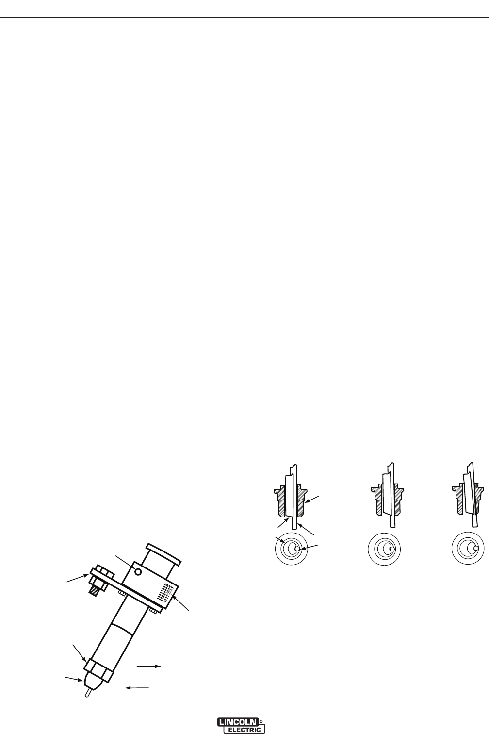
Because the electrode is held against one point of the
contact tip, it wears a groove at that point. When the
groove is about one half the diameter of the electrode,
rotate the contact tip to a new position per the instruc-
tions below. Careful positioning of the contact tip will
provide four to six wear spots depending upon the elec-
trode size.
When welding with the small diameter electrodes, it will
be necessary to change contact position more frequent-
ly since the amount of tip wear that can be tolerated is
much less. The tang should never be allowed to touch
the I.D. of the contact tip. If the groove is allowed to
wear until the tang touches the I.D. of the contact tip,
welding current passes through the tang. This causes
electrical wear and overheating of the tang and the con-
tact tip. See Figure C.7.
To rotate the tip, clip the end of the electrode and inch it
up until it is free of the contact tip. Loosen the locking
nut about one-half turn and pull the nozzle body to
relieve the pressure of the tang against the inside of the
contact tip hole. At this moment rotate the tip the proper
amount and then retighten the locking nut.
MAXSA™ 22 & 29 WIRE DRIVES
C
o
n
n
e
c
t
o
r
T
a
b
N
o
z
z
l
e
P
i
v
o
t
C
o
n
t
a
c
t
P
r
e
s
s
u
r
e
S
p
r
i
n
g
N
o
z
z
l
e
T
r
a
v
e
l
W
o
r
k
T
r
a
v
e
l
Locking
Nut
Contact
Tip
Tang
Electrode
New
Too Late
Time to
Rotate
Contact
Tip
FIGURE C.6
FIGURE C.7


