


C-9
ACCESSORIES
MAXsa™ 22 & 29 WIRE DRIVES
C-9
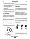
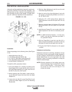
K29 VERTICAL HEAD ADJUSTER
Automatic welding applications frequently require rais-
ing and/or lowering of the feed head assembly. The
K29 provides an easy method of accomplishng this
task by simply turning a crank handle. A height varia-
tion of 4” (102mm) is possible with this attachment.
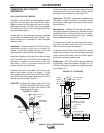
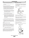
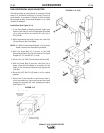
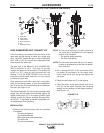
Installation
Check the package for the following items (See Figure
C.13):
1. Head Adjustment Lock (A)
2. 1/4” (6.3mm) diameter Roll Pin (B)
3. 12”-13x2.75” Hex Head Locking Screw (C)
4. Two adjustable clamps with hardware (D)
5. Vertical Head Lift Adjuster (E)
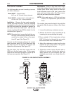
To install the K29, proceed as follows:
1. If the Feed Head (F) is already mounted to the
Head Support (E), be sure that the lock nut (H) on
the Feed Head Draw Bolt (J) is tight, and drive out
the Roll Pin (G) with a 5/16” punch.
2. While supporting the Feed Head, loosen the lock-
ing nut (H) and remove the head from the Head
Support (E).
3. Loosen the Lock Nut (K) on the Draw Bolt (L) and
remove the Head Support (E) from the Mounting
Bracket (M).
4. Slide the Head Adjustment Lock (A) over the end
of the Mounting Bracket (M).
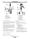
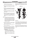
5. Align the hole of the Head Adjustnent Lock with
the groove in the Mounting Bracket and drive in
the 1/4” Roll Pin (B).
6. Using the 1/2” x 2.75 Locking Screw, tighten the
Head Adjustment Lock with the open slot in the up
position.
7. Slide the Vertical Head Lift Adjuster (E) into the
Mounting Bracket (M) and tighten the Draw Bolt
Nut (K).
8. Install the two Clamps (D), one on each side of the
Head Adjustment Lock with the hardware provid-
ed.
NOTE: If a K96 Horizontal Adjuster is to be used,
install it now per the instructions provided. If
not, proceed to Step 9.
9. With the Draw Bolt (J) and the Lock Nut (H) in
place, raise the Feed Head in to position on the up
and down lift shaft (N) and tighten the Lock Nut.
10. Drive the 5/16” Roll Pin (G) back in to itʼs original
position.
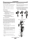
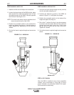
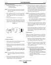
Adjustment and Locking
Rotational movement of the lifting mechanism is kept
to a minimum by the spring loaded, wedge shaped pin
(X) that is always in contact with the vertical slide. The
Socket Head Screw (Y) on the right side of the K29
housing is used as a locking mechanism to keep the
head at a desired height.
NOTE: Extreme tightening of the locking screw may
cause the wedge to jam so that the lift cannot
move in either direction. If this occurs, back
the screw out two turns and tap on it to
release the wedge.
FIGURE C.13 - K29