


C-6
ACCESSORIES
MAXsa™ 22 & 29 WIRE DRIVES
C-6
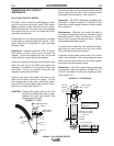
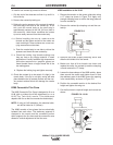
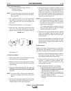
To install a new contact tip proceed as follows:
1. Clip the end of the electrode and inch it up until it is
free of the tip.
2. Remove the contact tip locking nut.
3. Relieve the spring pressure of the contact tip against
the steel tang in the hole of the contact tip. To do
this, push the nozzle body so the steel tang is
approximately centered in the 3/8” (9.5 mm) hole in
the contact tip. Under these conditions the contact
tip can be easily removed from the nozzle body.
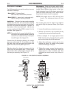
4 a. Before installing the new tip, make sure the
threads and the bottom surface of the nozzle are
clean and bright. These surfaces are current car-
rying areas and must be clean.
b. Push the nozzle body to one side to relieve the
pressure and insert the new contact tip.
5. a. Check the locking ring threads making sure
they are free or any foreign material. A small
application of locally available high temperature
anti-seize compound or graphite grease on
these threads insure a longer thread life of the
two mating parts.
b. Replace the locking ring and tighten securely.
6. Check the contact tip to be certain it is tight in the
nozzle body. If the tip is not tight, arcing will take
place between the tip contact surface and the noz-
zle contact surface which will damage the nozzle
body.
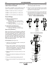
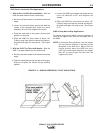
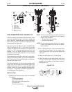
K285 Concentric Flux Cone
The K285 Concentric Flux Cone is designed to fit on a
K148 (with or without the K149 attachment) or on a
K129 Tiny Twin-Arc® nozzle. This attachment
deposits the flux so that it surrounds the electrode(s).
NOTE: If using a K149 extension, the electrical stick-
out will be limited to 4” (102mm).
The K285 consists of two pieces that are electrically
isolated from each other. The stationary segment is
clamped to the nozzle and the moveable portion
which supports the flux hose and the concentric cone
allows for vertical adjustment of the flux cone.
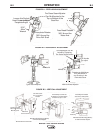
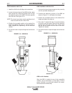
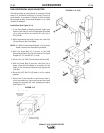
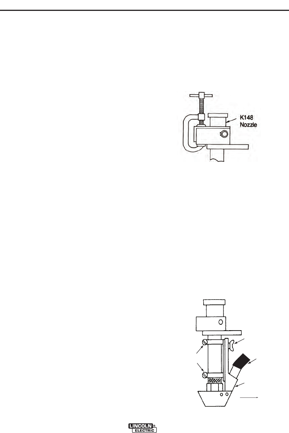
K285 Installation to the K148
1. Remove the tension on the center guide tube using
a “C” clamp as shown in Figure C.8. Apply only
enough clamping force to relieve the tang pressure
from the contact tip.
2. Remove the contact tip clamping nut and the con-
tact tip.
3. Remove the brass thread protecting collar and
slide the dirt shield off of the nozzle.
4. Make sure that all the threads are clean and
replace the collar, the contact tip and the clamping
nut and remove the “C” clamp.
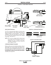
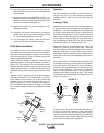
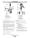
5. Loosen the hose clamps of the K285 entirely, place
them around the nozzle and tighten them so that
the stationary part of the K285 covers the opening
in the nozzle body as shown in Figure C.9.
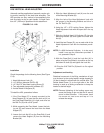
6. Position the moveable section to the desired flux
height and tighten the wing nut.
7. Cut the flux hose to required length and connect as
shown.
FIGURE C.8
FIGURE C.9 - K148
Travel
Direction
Wing Nut
Hose
Clamps
Flux
Hose
Moveable
Section