


C-3
ACCESSORIES
C-3
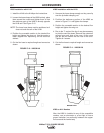
K226 CONTACT ASSEMBLY
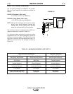
The K226 assemblies are used for welding at currents
from 600 to 1000 amps.
Model K226-T - (2 tapered jaws)
3/32” and 1/8” (2.4 and 3.2mm) electrode
Model K226-R - (1 tapered and 1 rectangular jaw)
1/8” thru 7/32” (3.2 - 5.6mm) electrode
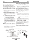
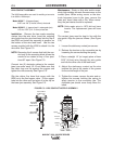
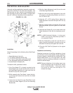
Installation - Remove the two nozzle mounting
clamps from the wire drive. Insert the outgoing
wire guide from the wire feed head into the top of
the K226 and install the assembly in position on
the bottom of the wire feed head. Use the two
screws provided with the K226 to attach it to the
wire drive. See Figure C.3.
NOTE: Removing the 4 screws that hold the noz-
zle body to the mounting block allows the
nozzle to be rotated to any of four posi-
tions 90° apart. See Figure C.3.
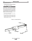
Connect two (2) electrode cables to the contact
jaws (one under each 1/2-13 nut. Make sure that
the cable lugs are flat against the copper and
tighten the nuts securely. See Figure C.3.
Slip the rubber flux hose that comes with the
K226 on to the flux hopper valve. Fit the copper
tube into the other end and place it in the clip on
the lower jaw assembly. See Figure C.3.
Maintenance - Rusty or dirty wire and/or exces-
sively high welding currents increase wear on the
contact jaws. When arcing occurs or the elec-
trode becomes loose in the jaws, remove the
jaws and ʻdressʼ them with a file. When neces-
sary, the jaw inserts should be replaced.
NOTE: Units made prior to 1979 did not have
inserts. The replacement jaws will have
them.
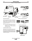
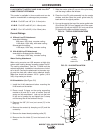
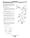
The contact jaws must be kept in line with the
wire guide. Align the jaws as follows: (See Figure
C.3)
1. Loosen the stationary contact jaw screws.
2. Release the tension on the moveable jaw by
loosening the screws holding the spring.
3 Place a straight 14” (or longer) piece of bare
5/32” (4.0mm) wire through the wire guide
and into the drive rolls of the feed head.
4. Adjust the stationary contact so the wire
touches the jaw at the center of the groove
for the entire length of the jaw.
5. Tighten the screws, remove the wire and re-
tighten the screws holding the spring to
apply tension to the moveable jaw. The
moveable jaw should move freely when fin-
ished.
MAXSA™ 22 & 29 WIRE DRIVES
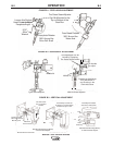
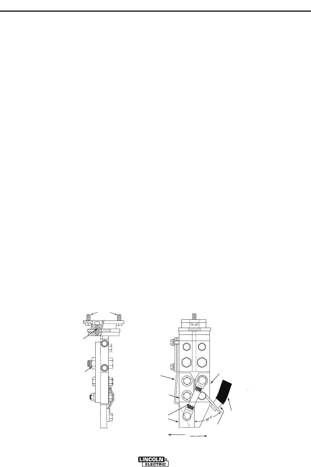
FIGURE C.3 - K226 CONTACT NOZZLE ASSEMBLY
Use to Mount
to Wire Drive
Remove(4)
Screws to
Rotate Nozzle
Attach Weld
Cables Here
K226-R
Only
Flux
Hose
Copper Tube
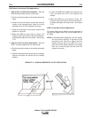
WORK
TRAVEL
NOZZLE
TRAVEL
Spring
Stationary
Contact
Moveable
Contact