


INSTALLATION
A-4 A-4
MULTI-SOURCE
Return to Section TOC Return to Section TOC Return to Section TOC Return to Section TOC
Return to Master TOC Return to Master TOC Return to Master TOC Return to Master TOC
FUSE AND WIRE SIZES
Protect the input circuit with the super lag fuses or
delay type circuit breakers listed on the Technical
Specifications page of this manual for the machine
being used. They are also called inverse time or ther-
mal/magnetic circuit breakers.
DO NOT use fuses or circuit breakers with a lower amp
rating than recommended. This can result in nuisance
tripping caused by inrush current even when machine
is not being used for welding at high output currents.
Use input and grounding wire sizes that meet local
electrical codes, or see the Technical Specifications
page in this manual.
INPUT AND GROUNDING
CONNECTIONS
Note: A qualified electrician should connect the
input power supply leads.
Input conductor is brought into the machine input box
area through a hole in the rear panel sized to accom-
modate 2" (trade size) conduit and fittings. This is more
than adequate for the largest conductors required.
Conductors must be lugged to attach to the three 3/8"
studs on the input reconnect panel and the 5/16"
ground stud marked with the symbol . The input volt-
age supplied determines the position required for the
reconnect panel jumper. The three ranges on the stan-
dard machine are 380-415, 440-460 and 550-575. The
machine is rated for 50 and 60 Hz operation. See the
Input Connection Diagram located on the inside of
Case Back Input Access Door.
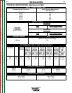
The conductor and fuse sizes in the Technical
Specification Section), are per the National Electrical
Code. The sizes are in American Wire Gauge (and the
next largest standard metric size in mm
2
). National and
local codes must be consulted before connecting a
machine.
Protect the input circuit with the super lag fuses or
delay type circuit breakers listed in the Technical
Specification Section. (They are also called inverse
time or thermal / magnetic circuit breakers.)
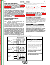
RECONNECT PROCEDURE
Multiple voltage machines are shipped connected to
the highest input voltage listed on the machine’s rating
plate. Before installing the machine, check that the
Reconnect Panel in the Input Box Assembly is con-
nected for the proper voltage.
Failure to follow these instructions can cause immedi-
ate failure of components within the machine.
-----------------------------------------------------------
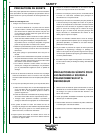
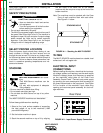
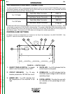
To reconnect a multiple voltage machine to a different
voltage, remove input power and follow the input
Connection Diagram located on the inside of the Case
Back Input Access Door. This connection diagram is
shown below.
CAUTION
WARNING
FIGURE A.3. - Input Connection Diagram
All input power must be electrically discon-
nected before touching reconnect panel.
1. Mount the movable reconnect bar to
the stationary reconnect panel as
shown, and secure firmly with the
three hex nuts provided.
2. Connect L1, L2, and L3 input supply
lines to the input side of the recon-
nect panel as shown.
3. Connect terminal marked to ground
per national electrode code.
550-575V Connection
440-460V Connection
380-415V Connection
INPUT
LINES
L3
L2
L1
W
V
U
INPUT
LINES
L3
L2
L1
W
V
U
INPUT
LINES
L3
L2
L1
W
V
U