


F-15 F-15
TROUBLESHOOTING & REPAIR
MULTI-SOURCE
Return to Section TOC Return to Section TOC Return to Section TOC Return to Section TOC
Return to Master TOC Return to Master TOC Return to Master TOC Return to Master TOC
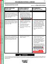
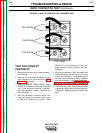
T3
T2
T1
U
V
W
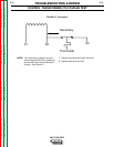
TOP VIEW
Test Points
Test Points
Test Points
TEST FOR CONTACT
CONTINUITY
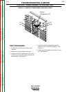
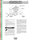
1. Disconnect the main input supply power to
the machine.
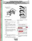
2. Remove the two leads connected to the
input contactor coil, #240 and #241. See
Figure F.3 for location.
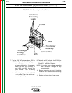
3. Using the external 120VAC supply, apply
120VAC to the leads of the input contactor
coil. If the contactor does NOT activate,
the input contactor is faulty. Replace the
input contactor.
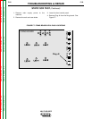
4. With the contactor activated, check the
continuity across the contacts. (Zero ohms
or very low resistance is normal.) See
Figure F.4. If the resistance is high, the
input contactor is faulty. Replace the input
contactor.
5. When the contactor is NOT activated, the
resistance should be infinite or very high
across the contacts. If the resistance is
low, the input contactor is faulty. Replace
the input contactor . See Input Contactor
Removal and Replacement Procedure.
6. Reconnect any leads previously removed.
Replace any cable ties and loom previous-
ly removed. Replace the roof and left case
side.
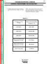
FIGURE F.4. INPUT CONTACTOR TEST CONNECTIONS
INPUT CONTACTOR TEST (Continued)