


F-58 F-58
TROUBLESHOOTING & REPAIR
MULTI-SOURCE
Return to Section TOC Return to Section TOC Return to Section TOC Return to Section TOC
Return to Master TOC Return to Master TOC Return to Master TOC Return to Master TOC
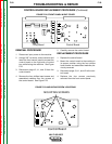
SCR BRIDGE / HEAT SINK ASSEMBLY REPLACEMENT PROCEDURE
INSTALLATION OF SCR OUTPUT
BRIDGE
NOTE: Upon reassembly, apply a thin layer of
Lincoln T12837 (Dow Corning #340)
heat sink compound to all bolted elec-
trical connections on the aluminum
heat sinks, including positive buss bar.
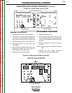
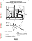
1. Carefully maneuver SCR bridge back into
original position.
2. Using a solder iron, reconnect lead #251 to
the main transformer and insulate.
3. Replace the two 9/16” mounting bolts pre-
viously removed. Be sure to position insu-
lation, bushing, washer, and nut correctly.
See Figure F.26.
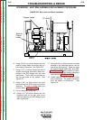
4. Replace the two 1/2” mounting bolts on
the right side of the machine previously
removed. These bolts mount the SCR
bridge to the main transformer. See
Figure F.27.
5. Replace any previously removed cable
ties.
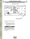
6. Replace the 3/8” mounting screw previ-
ously removed from the front of the
machine located behind the control panel.
7. Reconnect plug J4 to the firing board.
8. Replace the four screws previously
removed from the front control panel.
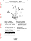
9. Reconnect the six copper transformer sec-
ondary leads previously removed.
10. Reconnect the two positive output leads
to the shunt.
11. Reconnect leads #264 and #301 previous-
ly removed from the thermostat.
12. Replace the case sides and roof.