


F-18 F-18
TROUBLESHOOTING & REPAIR
MULTI-SOURCE
Return to Section TOC Return to Section TOC Return to Section TOC Return to Section TOC
Return to Master TOC Return to Master TOC Return to Master TOC Return to Master TOC
MAIN TRANSFORMER (T1) VOLTAGE TEST (continued)
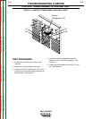
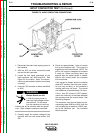
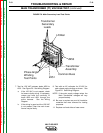
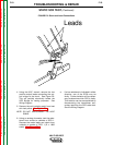
Reconnect Panel
Assembly
Input Contactor
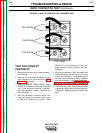
TEST PROCEDURE
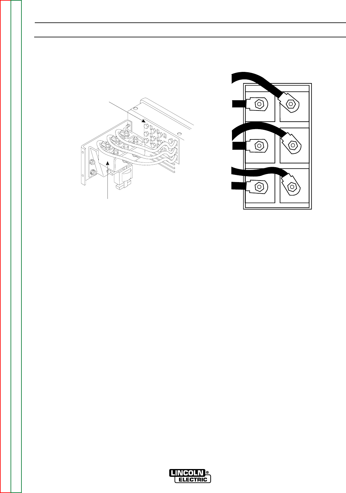
1. Disconnect main AC input power to the
machine.
2. Using a 3/8” nutdriver, remove roof and
sides of case cover.
3. Inspect the input contactor, reconnect
panel, and primary leads to the main trans-
former for loose or faulty connections. See
Figure F.5.
4. Carefully apply input power, turn on and
make sure the input contactor (1CR) ener-
gizes.
5. Carefully test with an AC voltmeter for the
proper main AC input voltage to the line
side of the input contactor (1CR). See
Wiring Diagram. See Figure F.5.
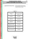
U to V
V to W
U to W
NOTE: If proper voltage is not present in any
or all of the three phases, check input
fuses and leads.
5. Test with an AC voltmeter for proper main
AC input voltage from the output side of
the input contactor (1CR). See Wiring
Diagram. See Figure F.5.
T1 to T2
T2 to T3
T1 to T3
a. If the correct voltage is present, the
contactor is working properly.
b. If the correct voltage is not present for
any or all of the three phases, the con-
tactor may be faulty. See Input
Contactor Test.
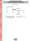
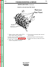
6. Test with an AC voltmeter for approximate-
ly 97 VAC from each of the six main trans-
former secondary leads to the common
buss connected to the negative output ter-
minal. See Figure F.6.
a. If one or more of the above voltage
tests are incorrect, check for loose or
faulty wiring. If the wiring is good,
then the main transformer may be
faulty.
NOTE: A long wire with a clip or a long probe
may be required to reach the lower
middle lead.
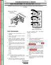
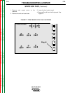
FIGURE F.5. Input Contactor, Reconnect Panel, and Primary Leads to Main Transformer
Locations
T3
T2
T1
U
V
W
TOP VIEW
INPUT CONTACTOR