


F-19 F-19
TROUBLESHOOTING & REPAIR
MULTI-SOURCE
Return to Section TOC Return to Section TOC Return to Section TOC Return to Section TOC
Return to Master TOC Return to Master TOC Return to Master TOC Return to Master TOC
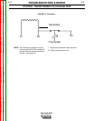
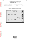
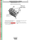
MAIN TRANSFORMER (T1) VOLTAGE TEST (continued)
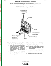
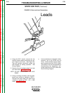
Transformer
Secondary
Leads
Lift Bail
Common Buss
Transformer
Assembly
#250
#251
Phase Angle
Winding
Test Points
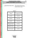
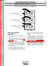
7. Test for 120 VAC between leads #250 to
#251. See Figure F.6. See Wiring Diagram.
a. If the 120 VAC is not present, check
for loose or faulty wiring. If necessary,
untape and track the continuity of
leads #250 and #251 through the
entire harness. See the Wiring
Diagram.
b. If the wiring is good and the 120 VAC
is not present, then the main trans-
former may be faulty.
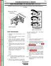
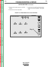
9. Test with an AC voltmeter for 32 VAC for
each phase angle winding as shown. See
Figure F.6. See Wiring Diagram.
NOTE: If the main supply voltage varies, the
Main Transformer voltages will vary
proportionately.
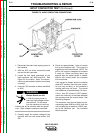
10. Be sure to replace any and all insulation
materials that were removed for testing
purposes.
11. Replace roof and sides of case cover.
FIGURE F.6. Main Secondary Lead Test Points