


F-54 F-54
TROUBLESHOOTING & REPAIR
MULTI-SOURCE
Return to Section TOC Return to Section TOC Return to Section TOC Return to Section TOC
Return to Master TOC Return to Master TOC Return to Master TOC Return to Master TOC
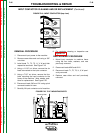
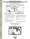
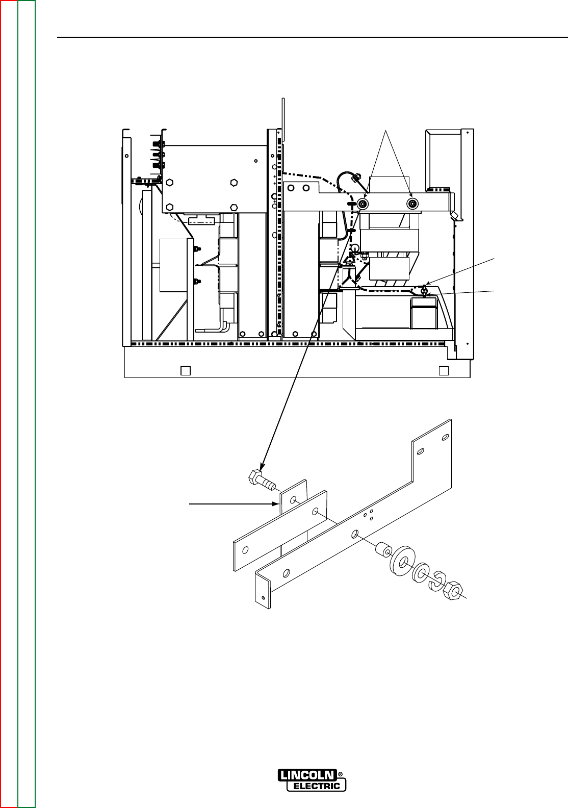
SCR BRIDGE / HEAT SINK ASSEMBLY REPLACEMENT PROCEDURE
REMOVAL PROCEDURE
1. Disconnect input power to the machine.
2. Using a 3/8” nut driver, remove the case
sides and roof.
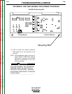
3. Locate, label, and remove leads #301 and
#264 from the thermostat. See Figure F.26.
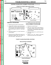
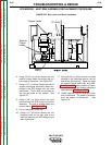
4. Lower the control panel using a 3/8” nut
driver.
5. Remove plug J4 from the firing board and
feed the disconnected plug down through
the hole in the bottom of the P.C. board
control box.
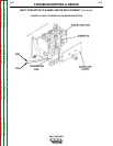
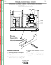
LEFT SIDELEFT SIDE
9/16" Bolts
#264
#301
FIGURE F.26. Bolt and Lead Locations
Bridge
Assembly
Mount