


F-37 F-37
FIRING BOARD TEST (Continued)
TROUBLESHOOTING & REPAIR
MULTI-SOURCE
Return to Section TOC Return to Section TOC Return to Section TOC Return to Section TOC
Return to Master TOC Return to Master TOC Return to Master TOC Return to Master TOC
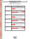
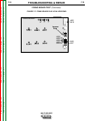
TABLE F.2. - LED 7, 8 and 9 Check List
IF
LED 7 is ON
LED 7 is OFF or is DIM-
MER than other LEDs
LED 8 is ON
LED 8 is OFF or is DIM-
MER than other LEDs
LED 9 is ON
LED 9 is OFF or is DIM-
MER than other LEDs
THEN
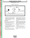
AC power is being supplied to the Firing Board from leads
#283 and #284 connected, through the resistor bank, to
the phase angle winding in the Main Transformer. See
Figure F.17.
Normal voltage at leads #283 to #284 is 25 VAC.
The proper AC voltage may not be reaching the Firing
Board. Check for loose or faulty connections. Perform
Main Transformer Test. Also check resistors R3 and R4
located in the resistor bank. Normal resistance is 50
ohms.
AC power is being supplied to the Firing Board from leads
#285 and #286 connected, through the resistor bank, to
the phase angle winding in the Main Transformer. See
Figure F.17.
Normal voltage at leads #285 to #286 is 25 VAC.
The proper AC voltage may not be reaching the Firing
Board. Check for loose or faulty connections. Perform
Main Transformer Test. Also check resistors R5 and R6
located in the resistor bank. Normal resistance is 50
ohms.
AC power is being supplied to the Firing Board from leads
#287 and #288 connected, through the resistor bank, to
the phase angle winding in the Main Transformer. See
Figure F.17.
Normal voltage at leads #287 to #288 is 25 VAC.
The proper AC voltage may not be reaching the Firing
Board. Check for loose or faulty connections. Perform
Main Transformer Test. Also check resistors R7 and R8
located in the resistor bank. Normal resistance is 50
ohms.